Low temperature double-layer capacitors

a capacitor and low temperature technology, applied in the direction of liquid electrolytic capacitors, casings/cabinets/drawers, electrical apparatus casings/cabinets/drawers, etc., can solve the problems of low temperature storage of electrical energy and delivery of electrical power, difficult to achieve, and other power sources such as radioisotope thermoelectric generators cannot provide high power levels. , to achieve the effect of reducing the melting point of the base solven

Active Publication Date: 2008-12-11
CALIFORNIA INST OF TECH
View PDF6 Cites 27 Cited by
  • Summary
  • Abstract
  • Description
  • Claims
  • Application Information

AI Technical Summary

Benefits of technology

[0021]In addition, embodiments of the invention may encompass an apparatus, comprising a first porous electrode means for conducting a charge, a second porous electrode means for conducting an opposing charge, an electrolyte solution means for soaking the first electrode means and the second electrode means to enable formation of an electrical double-layer at interfaces of both the first porous electrode means and the second porous electrode means with the electrolyte solution means and thereby exhibit a dielectric interaction between charged surfa

Problems solved by technology

The storage of electrical energy and delivery of electrical power at low temperatures is difficult to achieve.
In part, this is because most typical energy storage technologies, such as chemical batteries, utilize electrochemical processes which are highly temperature dependent and cannot provide high currents at lower temperatures.
In addition, other power sources such as radioisotope thermoelectric generators cannot provide high power levels.
Despite these favorable attributes, commercially available components employing non-aqueous electrolytes (e.g., from Maxwell Technologies or Cooper Bussman, two leading suppliers of double-layer capacitors) are generally limited to operation at temperatures greater than −40° C. due to the relatively high freezing point of the standard electrolytes used.
Despite the relatively rugged nature

Method used


Image

  • Low temperature double-layer capacitors
  • Low temperature double-layer capacitors
  • Low temperature double-layer capacitors

Examples


Embodiment Construction

[0031]1. Overview

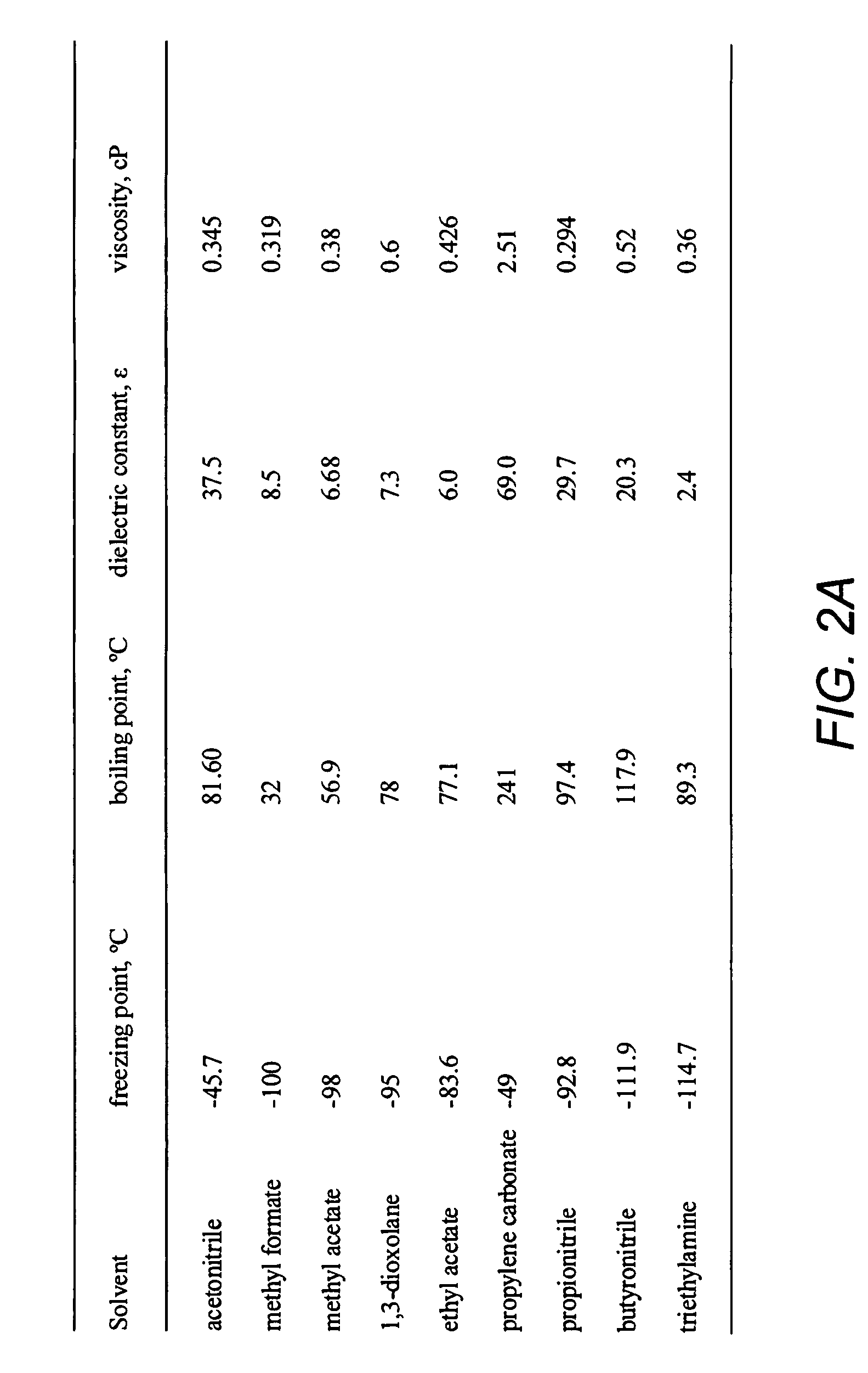
[0032]As previously mentioned, embodiments of the invention are directed to non-aqueous double-layer capacitors having an electrolyte system that operates below −40° C. and delivering useful cell characteristics such as capacitance and low ESR at these lower temperatures. This work may lend a greater understanding of fundamental cell processes (such as current leakage and the nature of the double layer), as well as lead to a practical device for low temperature operation in future space exploration robotic missions. Extension of the operating temperature to at least −55° C. (the required lower operating temperature limit for most space rated electronics) would make these components more appealing for space applications.

[0033]Some potential space applications for such double-layer capacitors include augmenting high specific energy, low temperature primary battery cells or in designing hybrid capacitor-secondary battery cell systems to extend cell life in robotic spac...


PUM

PropertyMeasurementUnit
Temperatureaaaaaaaaaa
Fractionaaaaaaaaaa
Fractionaaaaaaaaaa

Abstract

Double-layer capacitors capable of operating at extremely low temperatures (e.g., as low as −75° C.) are disclosed. Electrolyte solutions combining a base solvent (e.g., acetonitrile) and a cosolvent are employed to lower the melting point of the base electrolyte. Example cosolvents include methyl formate, ethyl acetate, methyl acetate, propionitrile, butyronitrile, and 1,3-dioxolane. An optimized concentration (e.g., 0.10 M to 0.75 M) of salt, such as tetraethylammonium tetrafluoroborate, is disolved into the electrolyte solution. In some cases (e.g., 1,3-dioxolane cosolvent) additives, such as 2% by volume triethylamine, may be included in the solvent mixture to prevent polymerization of the solution. Conventional device form factors and structural elements (e.g., porous carbon electrodes and a polyethylene separator) may be employed.

Description

CROSS-REFERENCE TO RELATED APPLICATIONS[0001]This application claims the benefit under 35 U.S.C. §119(e) of the following U.S. provisional patent applications, which are both incorporated by reference herein:[0002]U.S. Provisional Patent Application No. 60 / 933,323, filed Jun. 5, 2007, and entitled “LOW TEMPERATURE DOUBLE-LAYER CAPACITORS”, by Brandon et al. (Attorney Docket CIT-4753-P); and[0003]U.S. Provisional Patent Application No. 60 / 967,092, filed Aug. 31, 2007, and entitled “LOW TEMPERATURE DOUBLE-LAYER CAPACITOR TECHNOLOGY”, by West et al. (Attorney Docket CIT-4962-P).STATEMENT OF GOVERNMENT RIGHTS[0004]The invention described herein was made in the performance of work under a NASA contract, and is subject to the provisions of Public Law 96-517 (35 U.S.C. 202) in which the Contractor has elected to retain title.BACKGROUND OF THE INVENTION[0005]1. Field of the Invention[0006]This invention relates to electrical double-layer capacitors. Particularly, this invention relates to l...

Claims


Application Information

Patent Timeline
IPC IPC(8): H01G9/038
CPCH01G9/038H01G11/60Y10T29/417Y02E60/13H01G11/64H01G11/84H01G11/62
Inventor BRANDON, ERIK J.SMART, MARSHALL C.WEST, WILLIAM C.
Owner CALIFORNIA INST OF TECH
Why Eureka
Try Eureka