

Organic electroluminescent device
- Summary
- Abstract
- Description
- Claims
- Application Information
AI Technical Summary
Benefits of technology
Problems solved by technology
Method used
Image

Examples
example 1
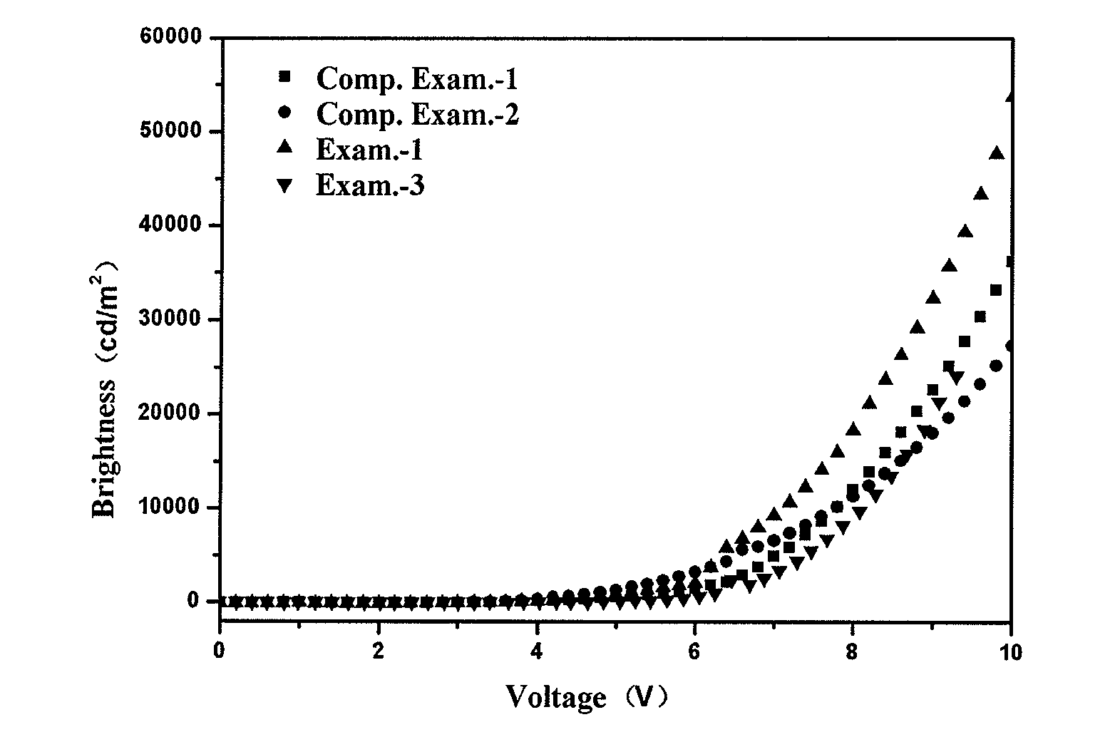
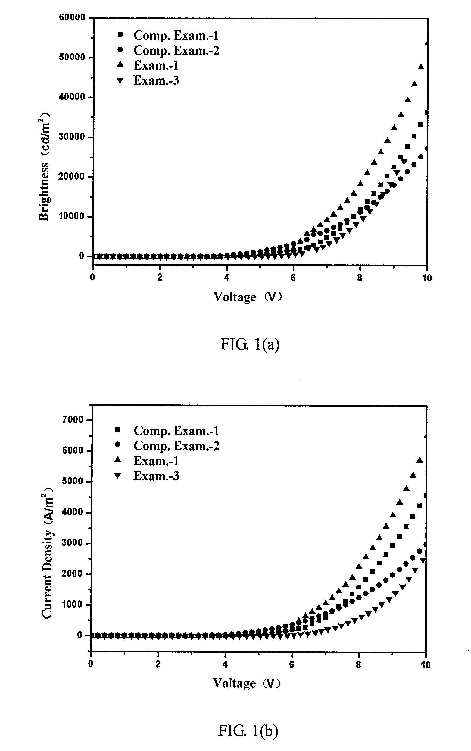
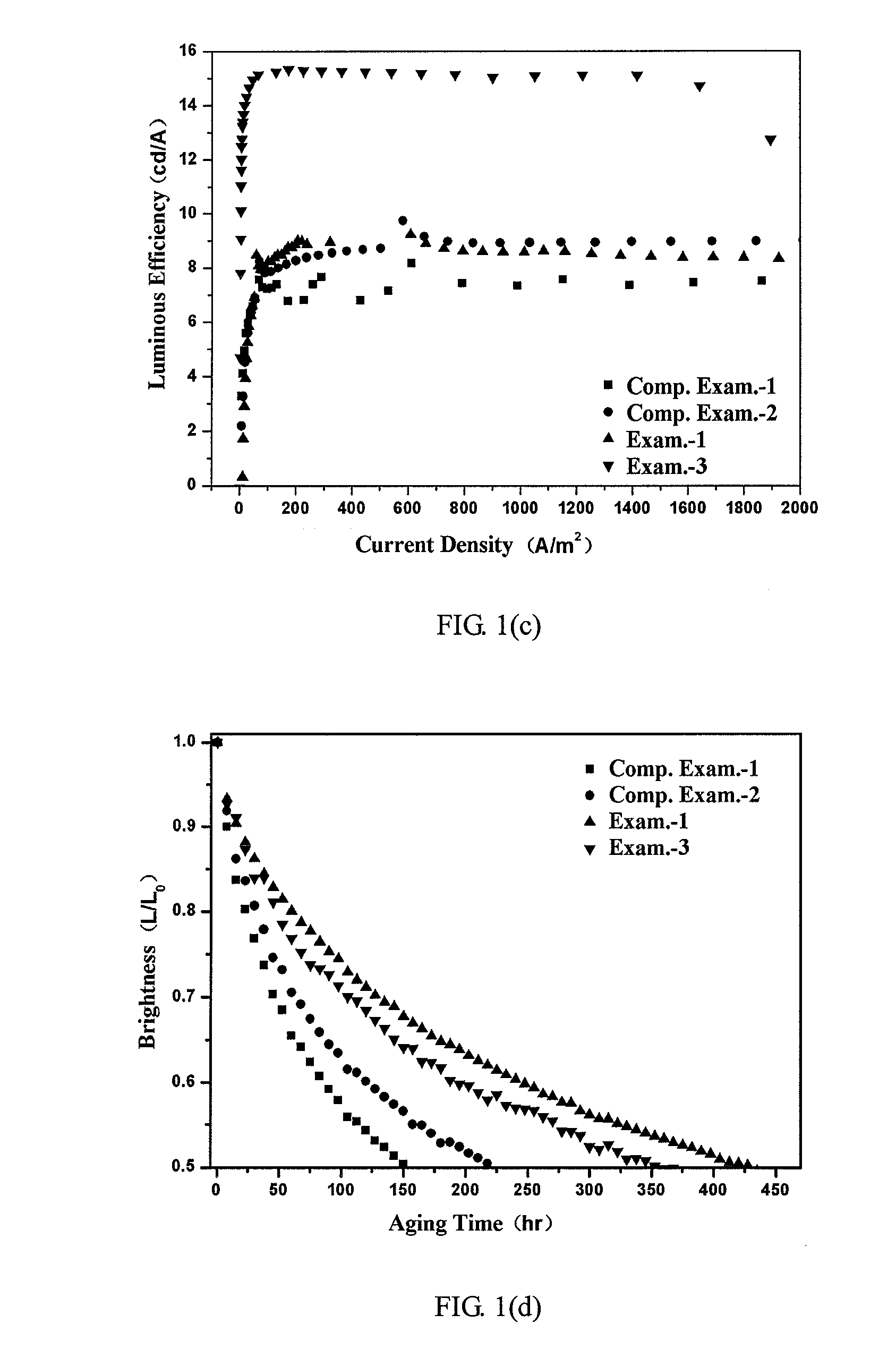
Exam.-1
[0044]Device Structure:
[0045]Glass / ITO / m-MTDATA(120 nm):BiF3[40%] / NPB(30 nm) / Alq3(30 nm):C545T[1%] / Alq3(20 nm) / LiF(0.5 nm) / Al(200 nm)
[0046]An organic electroluminescent device having the structure above is prepared by the following method.
[0047]The glass substrate is cleaned by thermal detergent ultrasonic and deionized water ultrasonic methods, and then dried under an infrared lamp. Then, the dried glass substrate is preprocessed by ultraviolet ozone cleaning and low energy oxygen ion beam bombardment, wherein the indium tin oxide (ITO) film on the substrate is used as an anode layer. The Sheet Resistance of the ITO film is 50 Ω, and its thickness is 150 nm.
[0048]The preprocessed glass substrate is placed in a vacuum chamber which is pumped to 1×10⁻⁵ Pa. A hole injection layer is deposited on the ITO anode by co-evaporating of m-MTDATA and BiF3 from separated crucible at an evaporation rate of 0.1 nm / s. The film thickness of the HIL is about 120 nm and the concentration of ...
example 2
Exam.-2
[0053]Device Structure:
[0054]Glass / ITO / m-MTDATA(120 nm): Bi2O3[40%] / NPB(30 nm) / Alq3(30 nm): C545T[1%] / Alq3(20 nm) / LiF(0.5 nm) / Al(200 nm)
[0055]A device is prepared in the same manner as in Example 1 except that the dopant material in HIL is changed to Bi2O3.
example 3
Exam.-3
[0056]Device Structure:
[0057]Glass / ITO / m-MTDATA(120 nm): Sm2(CO3)3[40%] / NPB(30 nm) / Alq3(30 nm): C545T[1%] / Alq3(20 nm) / LiF(0.5 nm) / Al(200 nm)
[0058]A device is prepared in the same manner as in Example 1 except that the dopant material in HIL is changed to Sm2(CO3)3.
PUM
 Abstract
Description
Claims
Application Information