
Porous Film and Multilayer Assembly Using the Same

Inactive Publication Date: 2009-01-08
DAICEL CHEM IND LTD
View PDF7 Cites 130 Cited by
  • Summary
  • Abstract
  • Description
  • Claims
  • Application Information

AI Technical Summary

Benefits of technology

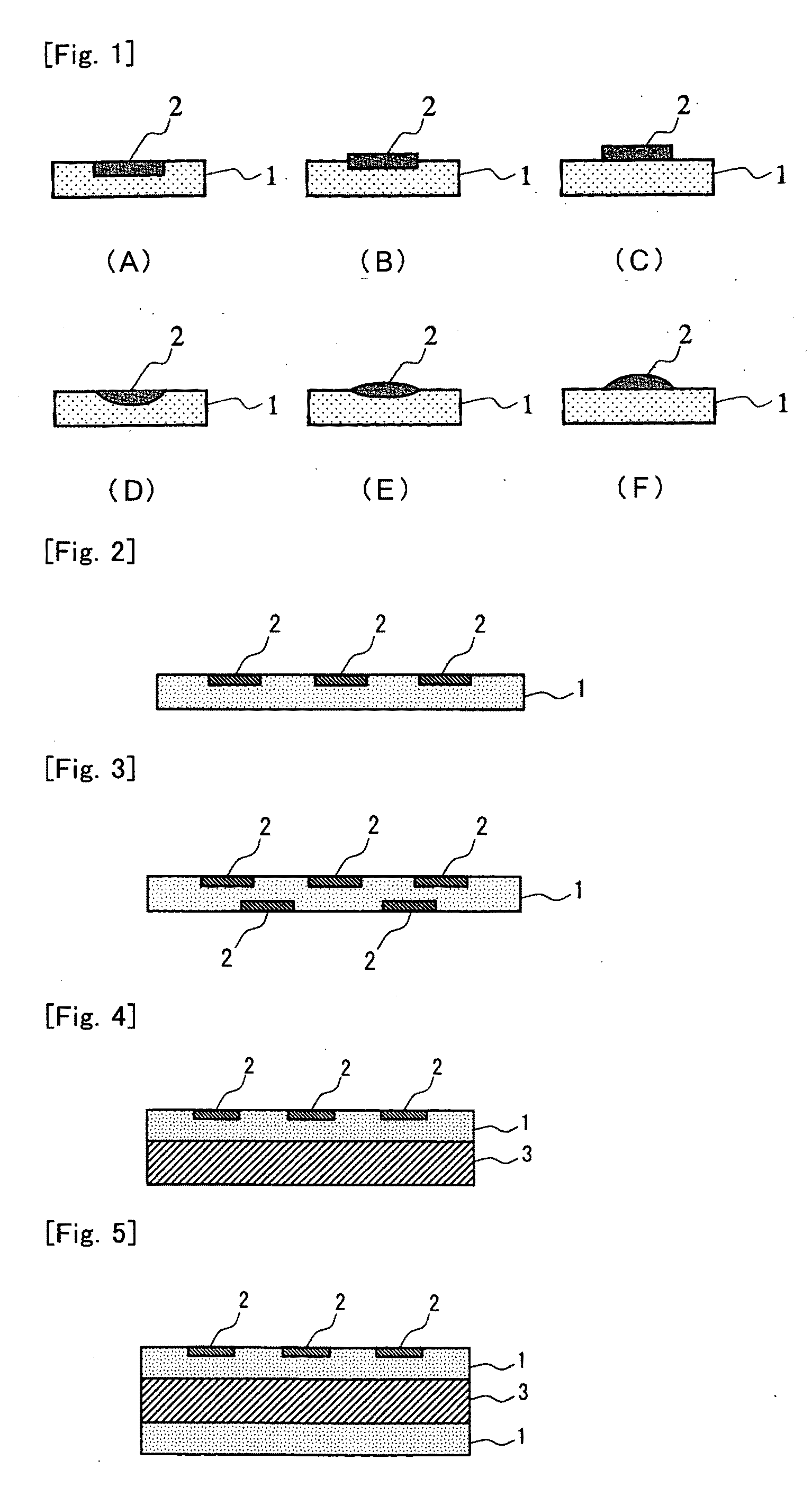
[0081]The multilayer assemblies according to the present invention each include a porous layer having a large number of micropores, are thereby satisfactorily flexible, and have excellent pore properties. In addition, they exhibit a sufficient strength even when having a porosity and much excel in folding endurance and handleability, because the porous layer is lined by the base. According to the present invention, multilayer assemblies having these characteristic properties and having homogeneous film quality can be easily and stably produced. The resulting multilayer assemblies have the characteristic properties and are usable typically as low dielectric constant materials, filters, separators, electrolyte membranes for fuel cells, catalyst bases (catalyst carriers), cushioning materials, ink receiving sheets, test papers (indicator papers), electric insulating materials, and thermal insulating materials. In addition, when pores of the porous layer are filled with a functional material, they are also widely usable as circuit substrates (circuit boards), radiators (heat sinks, radiator plates), electromagnetic regulators including electromagnetic shielding materials and electromagnetic absorbing materials, battery separators (separators for cells), capacitors (e.g., paper capacitors, plastic film capacitors, ceramic capacitors, mica capacitors, and electrolytic capacitors), cell-culture base materials, and catalyst bases (catalyst carriers).
[0082]The circuit boards according to the present invention include a porous film layer having a large number of uniformly dispersed continuous micropores (communicating micropores); and conductive interconnections arranged on at least one side of the porou

Problems solved by technology

The dry layer transition technique induces microphase separation by evaporating the solvents from the coat, and the resin (polymeric compound) constituting the porous layer is limited to those soluble in low-boiling-point good solvents.
Accordingly, it is difficult to use, in this technique, polymeric compounds that have large molecular weights and are inherently sparingly soluble in such solvents.
This, however, results in disadvantages.
Typically, it is difficult to give a coat with a sufficient thickness; of components of the coat, a component that has not been removed upon evaporation of the solvents remains in the resulting porous layer, and this impedes the use of nonvolatile additives; the structure of the porous layer is significantly affected by heating conditions and environmental conditions during production processes, and this impedes stable production and tends to result in variation in properties of the film (film quality), such as pore diameter, rate of open area, porosity, and thickness.
This technique helps to stabilize the environmental conditions during production, but it fails to solve the above problems related to the dry phase inversion technique, because even the wet phase inversion fundamentally employs the procedure of drying by heating.
However, when pitches between conductive interconnections are made finer, the surface roughening of the copper foil causes cutting or peeling (delamination) of interconnections upon etching, due to roughness of the copper foil.
In contrast, when copper foil without surface roughening is used, etching is conducted satisfactorily, but the adhesion between the insulator and the copper foil is insufficient, and thereby the overall interconnections are likely to delaminate.
This will cause cutting or delamination of the interconnections when the pitches between interconnections are made finer.
Accordingly, copper foil should have a smaller thickness so as to make pitches finer, but it is difficult to produce and handle such thin copper foil.
It is therefore believed that the current subtractive technique has limits on reduction of pitches.
When fine interconnections are formed, however, this technique causes, for example, linkage between interconnections due typically to print feathering.
Although the green sheet of the powder mixture excels in printability of fine interconnections, this method requires a firing process at temperatures near to 1000° C., resulting in increased cost.
In addition, the product lacks flexibility and is brittle.
This method, however, requires a laser beam irradiation process, and thereby suffer from low productivity and increased cost.
In addition, it requires a sophisticated technique for placing the ink into the trench pattern and is not suitable for mass production.
According to this technique, however, the resulting primary layer has low strength and is not usable as an interconnection material, because the layer is formed by the application of particles.

Method used


Image

  • Porous Film and Multilayer Assembly Using the Same
  • Porous Film and Multilayer Assembly Using the Same
  • Porous Film and Multilayer Assembly Using the Same

Examples


example 1

[0434]A material composition for film formation was prepared by adding 30 parts by weight of a polyvinylpyrrolidone (having a molecular weight of 5×10⁴) as a water-soluble polymer to 100 parts by weight of a polyamideimide resin solution (supplied by Toyobo Co., Ltd. under the trade name of “VYLOMAX HR11NN”; having a solid content of 15 percent by weight and a solution viscosity of 20 dPa·s / 25° C. in a solvent of NMP). While holding at 25° C., this material composition was cast onto PET film (Type S, 100 μm thick) supplied by Teijin DuPont Films Japan Limited as a base, using a film applicator under conditions of a gap (clearance) between the film applicator and the base of 127 μm. Immediately after casting, the article was placed in a vessel and held at a temperature of 50° C. and humidity of about 100% for 4 minutes. The article was then immersed in water for coagulation, subjected to air drying at room temperature without peeling off from the base, and thereby yielded an assembly...

example 2

[0436]An assembly including a base and a porous layer arranged thereon was prepared by the procedure of Example 1, except for using the water-soluble polymer in an amount of 33.3 parts by weight and carrying out casting under a condition of a gap between the film applicator and the PET base film of 102 μm. The porous layer had a thickness of about 35 μm, and the assembly had a total thickness of about 135 μm.

[0437]The prepared assembly was subjected to a tape peeling test to find that the base and the porous layer suffered from no interfacial delamination therebetween. This assembly was electron-microscopically observed to find that the porous layer was in intimate contact with the base, had an average pore diameter of pores appearing in its surface of about 0.5 μm, was substantially homogenous inside thereof, and contained entirely dispersed continuous micropores with an average pore diameter of about 0.5 μm. The porous layer had an internal porosity of 70%.

example 3

[0438]An assembly including a base and a porous layer arranged thereon was prepared by the procedure of Example 1, except for using the water-soluble polymer in an amount of 40 parts by weight and carrying out casting under a condition of a gap between the film applicator and the PET base film of 51 μm. The porous layer had a thickness of about 15 μm, and the assembly had a total thickness of about 115 μm.

[0439]The prepared assembly was subjected to a tape peeling test to find that the base and the porous layer suffered from no interfacial delamination therebetween. This assembly was electron-microscopically observed to find that the porous layer was in intimate contact with the base, had an average pore diameter of pores appearing in its surface of about 0.3 μm, was substantially homogenous inside thereof, and contained entirely dispersed continuous micropores with an average pore diameter of about 0.3 μm. The porous layer had an internal porosity of 70%.


PUM

PropertyMeasurementUnit
Lengthaaaaaaaaaa
Lengthaaaaaaaaaa
Lengthaaaaaaaaaa

Abstract

[Object] To provide a multilayer assembly that excels in pore properties, is flexible, and is satisfactorily handled and processed; and a method of producing the multilayer assembly.[Solving Means] A multilayer assembly includes a base and, arranged on at least one side thereof, a porous layer and has a large number of continuous micropores with an average pore diameter of 0.01 to 10 μm. The multilayer assembly suffers from no interfacial delamination between the base and the porous layer when examined in a tape peeling test according to the following procedure:Tape Peeling TestA 24-mm wide masking tape [Film Masking Tape No. 603 (#25)] supplied by Teraoka Seisakusho Co., Ltd. is applied to a surface of the porous layer of the multilayer assembly and press-bonded thereto with a roller having a diameter of 30 mm and a load of 200 gf to give a sample; and the sample is subjected to a T-peel test with a tensile tester at a peel rate of 50 mm / min.

Description

TECHNICAL FIELD[0001]The present invention relates to multilayer assemblies each including a base and a porous layer. The porous layer is arranged on at least one side of the base, and has a number of continuous micropores. The present invention further relates to production methods of the multilayer assemblies; composite materials using these multilayer assemblies; and production methods of the composite materials. By directly utilizing properties of pores in their porous layer or by filling the pores with a functional material and utilizing properties of the functional material, the multilayer assemblies are usable as a wide variety of base materials (base materials) typically for circuit substrates (circuit boards); radiators (heat sinks and radiator plates); electromagnetic regulators such as electromagnetic shielding materials and electromagnetic absorbing materials; battery separators; capacitors such as paper capacitors, plastic film capacitors, ceramic capacitors, mica capac...

Claims


Application Information

Patent Timeline
IPC IPC(8): H05K1/11H05K1/00H05K3/10B32B3/26B32B3/10B29C39/02B05D3/06B05D5/12
CPCB32B5/18B32B15/08H05K1/036H05K1/0366H05K1/0393Y10T428/24917H05K3/185H05K2201/0116Y10T29/49155Y10T428/24331Y10T428/24802H05K3/12Y10T428/249979H05K1/03H05K3/00
Inventor SHIMIZU, KIYOSHIYAMATO, YO
Owner DAICEL CHEM IND LTD
Learn More