Coating on a Medical Substrate and a Coated Medical Product

a medical substrate and coating technology, applied in the field of coating on the medical substrate and coating on the medical product, can solve the problems of large vacuum pumping period, time-consuming, high-volume vacuumed chamber, and inability to industrialize the coating of most of the present metal products, so as to reduce the torsional strength, enhance the properties, and increase the operation time

Inactive Publication Date: 2009-01-08
PICODEON OY
View PDF22 Cites 21 Cited by
  • Summary
  • Abstract
  • Description
  • Claims
  • Application Information

AI Technical Summary

Benefits of technology

[0001]The invention relates generally to a method for coating surfaces of medical products, e.g. articulating surfaces of a joint or bone screws. The invention also relates to products coated by the method. The invention has many advantageous effects such as high coating production rate, excellent coating properties and low manufacturing costs.
[0002]Several screw-dependent factors such as material of the screw, the screw diameter and length, the length of the threaded part, and the shape of the threads affect the forces experienced by the screws. Also the properties of the bone, such as the thickness of cortices and the density of bone, influence the forces required in screw installation and pullout. Screw failures during installation increase operation time and require the drilling of several holes in bone. Since drilling a hole into a bone reduces its torsional strength by 10-40% depending on the screw / bone diameter rate, it is essential to avoid screw failures during operations. Although current biomaterials are compatible for orthopaedic implants, various techniques are still used to enhance their properties. Different applications require specific properties even from the same material: in some cases implant is expected to stimulate bone ingrowth and increase attachment, but on the other hand inertness and low degradation rate may also be favourable in certain sections of the implant. Bone ingrowth and attachment can be enhanced by rough surfaces or textures on the implants. These surface conditions are achieved, for example, by different kinds of coating techniques or by etching. Smooth surfaces for preventing corrosion can be prepared by chemical or physical vapour deposition techniques. Amorphous diamond (AD) coatings can be produced by filtered pulsed arc discharge method which is one of the physical vapour deposition techniques. AD coating is reported to be even as hard as natural diamond, inert coating with low friction. Therefore, AD coatings should reduce the number of screw failures during installation as high torques leading to screw failures might be avoided. Also late removal of the screws is easier as less corrosion is expected.Hip Implants
[0003]In total hip replacements, the bulk properties of materials, such as proper elasticity and hardness, are important. However, the material interacts with the body mainly at the surfaces. Wear and corrosion are initiated at the surfaces also. Therefore, the control of surface properties using different kinds of treatments or coatings may improve total hip replacements considerably. Until now, the surface treatments most studied included ion implantation and methods to control surface topography such as grit or sand blasting or plasma treatments. Among the large variety of coatings, hydroxyapatite, titanium oxide and nitride, zirconium oxide, pyrolytic carbon, and diamondlike carbon coatings have shown the most promising results. These coatings mainly are used to enhance bone growth; to minimize friction, wear, and corrosion; and to improve biocompatibility of total joint prostheses. The potential of novel coatings to solve some present problems in joint prostheses is discussed based on the structure and properties of different kind of coatings. It can be concluded that currently coating methods exist to improve the tribological performance and longevity of the total hip replacements. However, coatings must fulfill two essential requirements for successful long-term performance: no delamination in biochemical and biomechanical environments and sufficient protection of substrate from corrosion. These requirements have turned out to be an obstacle for development of reliable coating solutions for many medical applications.
[0004]Any implant material can be divided into two characteristic components: bulk material, which mainly is responsible for the mechanical and structural properties; and surface layer material, which interacts with the biologic environment. Throughout the history of total hip replacement (THR), the focus in material development has been the improvement of bulk properties of metals and, more recently, those of ceramics and polymers. For example, in the case of metals, minor improvements have been reached by alloying and novel processing techniques. Both of these approaches enhance the control of microstructure and composition, which are reflected in hardness and wear or corrosion resistance. For example, the yield strength of Co—Cr alloys have been improved from the typical values of cast alloys (450 MPa) to about 1350 MPa for high-temperature isostatic pressing alloys. Similar improvements have been achieved with Ti alloys and stainless steel, especially using mechanical deformation hardening. In the case of polyethylene (PE), the main achievement has been well-controlled cross-linking to enhance mechanical properties, especially wear resistance.
[0005]On the other hand, the properties of material surfaces have a major effect on interaction with tissues or components of modular prostheses. Novel techniques for surface treatment and deposition can be used to modify the surface of the implant, for example, to protect the implant from degradation and corrosion, to improve the surface structure or chemistry for tissue integration, or to increase wear resistance and to control friction at the interfaces. In most cases, these additional treatments can be used for existing clinically tested implant designs and bulk materials without adverse effects on component dimensions or bulk material properties.Motivation for Coatings
[0006]Although bulk material properties have a major effect, for example, on elasticity or shock absorption properties of implants, properties of the surface layer are relevant for optimal behavior of each section of an implant. Low friction and wear rate are desirable at articulating surfaces and also at the other interfaces with micromotion between different components. Wear leads to release of debris particles to adjacent tissues, which can eventually cause aseptic loosening of an implant. Abrasive and adhesive wear are typical wear mechanisms. Abrasive wear (scratching) can be minimized using hard coatings or surface layers. Adhesive wear is related to sticking together of sliding surfaces, which can shear the softer material, in this case ultra-high molecular weight polyethylene (UHMWPE). In principle, adhesive wear could be minimized using materials with good wetting characteristics.

Problems solved by technology

Neither recent high-technological coating methods) nor present coating techniques related to laser ablation either in nanosecond or cold ablation range (pico-, femto-second lasers) can provide any feasible method for industrial scale coating of articulating surfaces of medical products.
The present CVD- and PVD-coating technologies require high-vacuum conditions making the coating process batch wise, thus non-feasible for industrial scale coating of most of the present metal products.
Moreover, the distance between the metal material to be coated and the coating material to be ablated is longs typically over 50 cm, making the coating chambers large and vacuum pumping periods time- and energy-consuming.
Such high-volume vacuumed chambers are also easily contaminated with coating materials in the coating process itself requiring continuous and time-consuming cleaning processes.
All this makes the coating of articulating surfaces with present method very slow, and thus increase heavily the price of the products making them unavailable for most of the mankind.
While trying to increase the coating production rate in present laser-assisted coating methods, various defects such as pinholes, increased surface roughness, decreased or disappearing optical properties, particulates on coating surface, particulates in surface structure affecting corrosion pathways, decreased surface uniformity, decreased adhesion, unsatisfactory surface thickness and tribological properties etc. take place.

Method used


Image

  • Coating on a Medical Substrate and a Coated Medical Product
  • Coating on a Medical Substrate and a Coated Medical Product
  • Coating on a Medical Substrate and a Coated Medical Product

Examples


example of invention — 1

Example of Invention—1

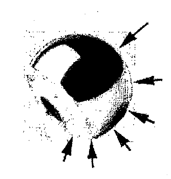
[0097]FIG. 14a demonstrates a target material ablated with pico-second-range pulsed laser employing rotating scanner with speed accomplishing the ablation of target material with slight overlapping of adjacent pulses, avoiding the problems associated with prior art galvano-scanners. FIG. 14b shows enlarged picture of one part of the ablated material, clearly demonstrating the smooth and controlled ablation of material on both x- and y-axis and thus, generation of high quality, particle-free plasma and further, high quality thin-films and coatings. FIG. 14c demonstrates one example of possible x- and y-dimensions of one single ablation spot achieved by one or few pulses. Here, it can be clearly seen, that the invention accomplishes the ablation of material in a manner wherein the width of the ablated spot is always much bigger than the depth of the ablated spot area. Theoretically, the possible particles (if they would be generated) could now have a maximum size...

example of invention — 2

Example of Invention—2

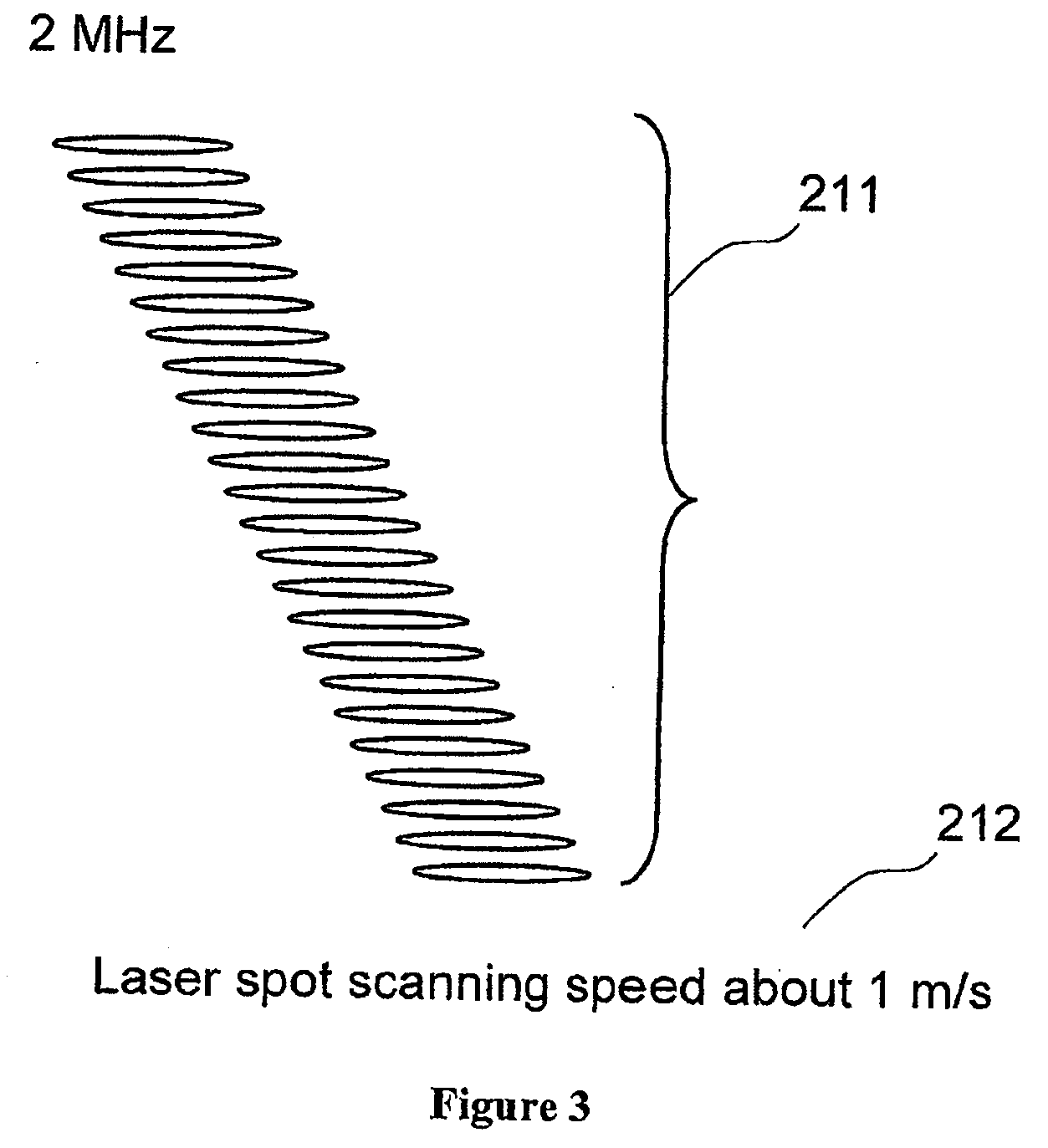
[0098]FIG. 15 demonstrates an example wherein coating is carried out by employing a pico-second USPLD-laser and scanning the laser pulses with turbine scanner. Here, the scanning speed is 30 m / s, the laser spot-width being 30 μm. In this example, there is an ⅓ overlapping between the adjacent pulses.

EXAMPLES OF INVENTION—COATED PRODUCTS

[0099]None of the prepared coating samples contained any pinholes due to deposition on examines surfaces of prepared coatings. Some of the samples were produced by employing state of the art galvano-scanners, some by employing rotating turbine scanner. When employing turbine scanner, pulse repetition rates exceeding 1 MHz could be employed.

example 1

Ceramic Coatings for Different Kind of Materials

[0100]Different kind of materials can be utilized in medical applications: metals, ceramics, polymers and composites. In this example, examples from different material groups were selected including silicon, Ta, Ti, stainless steel, CoCrMo, alumina, glass, polycarbonate, polyimide and polyethylene. Samples had a polished, nearly a mirror-line surface finish. They were washed with acetone and ethanol. The samples were loaded in a vacuum chamber and pumped down to a vacuum better than 10−4 mbar. Then they were coated with a ceramic coating using an ultra short pulse laser ablation. Fiber laser gave a 15-20 ps pulse with a frequency in range 1-4 MHz. A single pulse energy was varied in the range 0-5 μJ and the laser spot was focused by proper lenses in a diameter in the range 10-40 μm depending on the case. The ceramic target materials included titania, yttria stabilized zirconia (Y—ZrO2), yttria / alumina (YAG), alumina / titania (ATO), grap...


PUM

PropertyMeasurementUnit
frequencyaaaaaaaaaa
thicknessaaaaaaaaaa
thicknessaaaaaaaaaa

Abstract

The invention relates in general level to a method for coating articulating surfaces of medical products. The invention also relates to coated medical products manufactured by the method. The coating is carried out by employing ultra short pulsed laser deposition wherein pulsed laser beam is preferably scanned with a rotating optical scanner including at least one mirror for reflecting the laser beam. The invention has several both industrially and qualitatively advantageous effects such as high coating production rate, excellent coating properties and overall low manufacturing costs.

Description

FIELD OF INVENTION[0001]The invention relates generally to a method for coating surfaces of medical products, e.g. articulating surfaces of a joint or bone screws. The invention also relates to products coated by the method. The invention has many advantageous effects such as high coating production rate, excellent coating properties and low manufacturing costs.BACKGROUNDCoating of Medical ProductsBone Screws[0002]Several screw-dependent factors such as material of the screw, the screw diameter and length, the length of the threaded part, and the shape of the threads affect the forces experienced by the screws. Also the properties of the bone, such as the thickness of cortices and the density of bone, influence the forces required in screw installation and pullout. Screw failures during installation increase operation time and require the drilling of several holes in bone. Since drilling a hole into a bone reduces its torsional strength by 10-40% depending on the screw / bone diameter...

Claims


Application Information

Patent Timeline
Patent Type & Authority Applications(United States)
IPC IPC(8): A61B17/58A61L27/30B23K26/06C23C14/28
CPCA61B17/86Y10T428/26A61F2/30767A61F2/3094A61F2/34A61F2/38A61F2002/30929A61F2002/3097A61F2002/3611A61F2310/00395A61F2310/00574A61F2310/00598A61F2310/0073A61F2310/00856A61L27/30B23K26/0635B23K26/0815B23K26/34C23C14/0036C23C14/0611C23C14/0658C23C14/083C23C14/16C23C14/28B23K26/3206B23K26/322B23K26/3246B23K26/3266Y10T428/24331Y10T428/265A61B2017/00836B23K26/32B23K26/324B23K26/0821B23K26/0624B23K2103/05B23K2103/08B23K2103/14B23K2103/18B23K2103/26B23K2103/42B23K2103/50B23K2103/52B23K26/064
Inventor RUUTTU, JARILAPPALAINEN, REIJOMYLLYMAKI, VESAPULLI, LASSEMAKITALO, JUHA
Owner PICODEON OY
Why Eureka
Try Eureka