Method for the preparation of tube-type porous biodegradable scaffold having double-layered structure for vascular graft

Inactive Publication Date: 2009-01-08
KOREA INST OF SCI & TECH
1 Cites 75 Cited by

AI-Extracted Technical Summary

Problems solved by technology

As well, blood leakage, which may occur early after implantation, is a critical factor that influences the success of implantation of artificial blood vessels.
Conventional prosthetic vascular grafts made of expanded polytetrafluoroethylene (ePTFE) and polyethylene terephthalate (PET) satisfy the above requirements, but cannot be used in practice as tissue-engineered artificial blood vessels for inducing regeneration of the body blood tissue because the materials are non-degradable in the body.
Currently available artificial blood vessels, achieved through tissue engineering technologies using stem cells, have been limited in the clinical application thereof to the vena cava and the pulmonary artery, which are at re...

Method used

[0026]The porogen, which is mixed with the biodegradable polymer solution, is employed to the formation of micropores when an inner porous coating layer is formed on a cylindrical shaft. The size and form of pores may be controlled by varying the size, kind and amount of the porogen. This is critical for preventing the leakage of blood from the porous scaffold.
[0028]At step (2) of the method, a cylindrical shaft is coated with the polymer/porogen mixture obtained at step (1) in order to form an inner porous coating layer containing micropores. The micropores play an important role in preventing the leakage of blood.
[0034]In addition, the coagulation rate of the spun biodegradable polymer in the non-solvent coagulation bath is a critical factor in the attachment of the gel-phase fibrous polymer, formed through phase separation, to the inner porous layer containing micropores coated onto the shaft. The attachment between the fibrous polymer and the inner porous layer should be suitably maintained in order to construct a porous scaffold having uniform pore size and good pore interconnectivity. The attachment is induced by the solvent remaining in the fibrous polymer gel. That is, when the fibrous polymer gel is wound around the inner porous coating layer to thus form an outer layer, the remaining solvent melts the inner polymer layer, leading to attachment between the inner and outer layers. The coagulation rate of the spun biodegradable polymer in the non-solvent coagulation bath may be controlled depending on the kind and stirring rate of the non-solvent solution. To achieve a desired coagulation rate of the biodegradable polymer, it is preferable to employ a solvent which is able to induce the attachment between the gel-phase polymer fibers and the attachment between the fibrous polymer and the inner porous coati...

Benefits of technology

[0009]Accordingly, the present invention aims to provide a porous scaffold for use as an artificial vascular graft and a preparation method thereof, the scaffold having good pore ...

Abstract

Disclosed herein are a tube-type porous scaffold having a double-layered structure for use as an artificial vascular graft and a preparation method thereof. The method comprises (1) dissolving a biodegradable polymer in an organic solvent and mixing the polymer with a porogen so as to provide a polymer/porogen mixture; (2) coating a cylindrical shaft with the polymer/porogen mixture so as to form an inner porous coating layer; (3) preparing a biodegradable polymer gel by dissolving a biodegradable polymer in an organic solvent; (4) spinning down the biodegradable polymer gel in a non-solvent coagulation bath in which the cylindrical shaft having the inner porous coating layer, obtained at step (2), is immersed and rotated to form gel-phase fibers and allowing the gel-phase fibers to wind around the inner porous coating layer of the rotating shaft so as to form an outer polymer fibrous layer; and (5) separating the double-layered porous scaffold, formed on the shaft, from the shaft and removing the organic solvent and the porogen from the scaffold. Since the porous scaffold has a double-layered structure consisting of an inner porous coating layer containing micropores and a gel-phase outer polymer fibrous layer, it has high pore interconnectivity and mechanical strength, which effectively prevents the leakage of blood, and has high cell seeding and proliferation efficiencies, thereby being useful as a tissue-engineered artificial vascular graft.

Application Domain

Technology Topic

Layered structurePolymer dissolution +20

Image

  • Method for the preparation of tube-type porous biodegradable scaffold having double-layered structure for vascular graft
  • Method for the preparation of tube-type porous biodegradable scaffold having double-layered structure for vascular graft
  • Method for the preparation of tube-type porous biodegradable scaffold having double-layered structure for vascular graft

Examples

  • Experimental program(4)

Example

Example 1
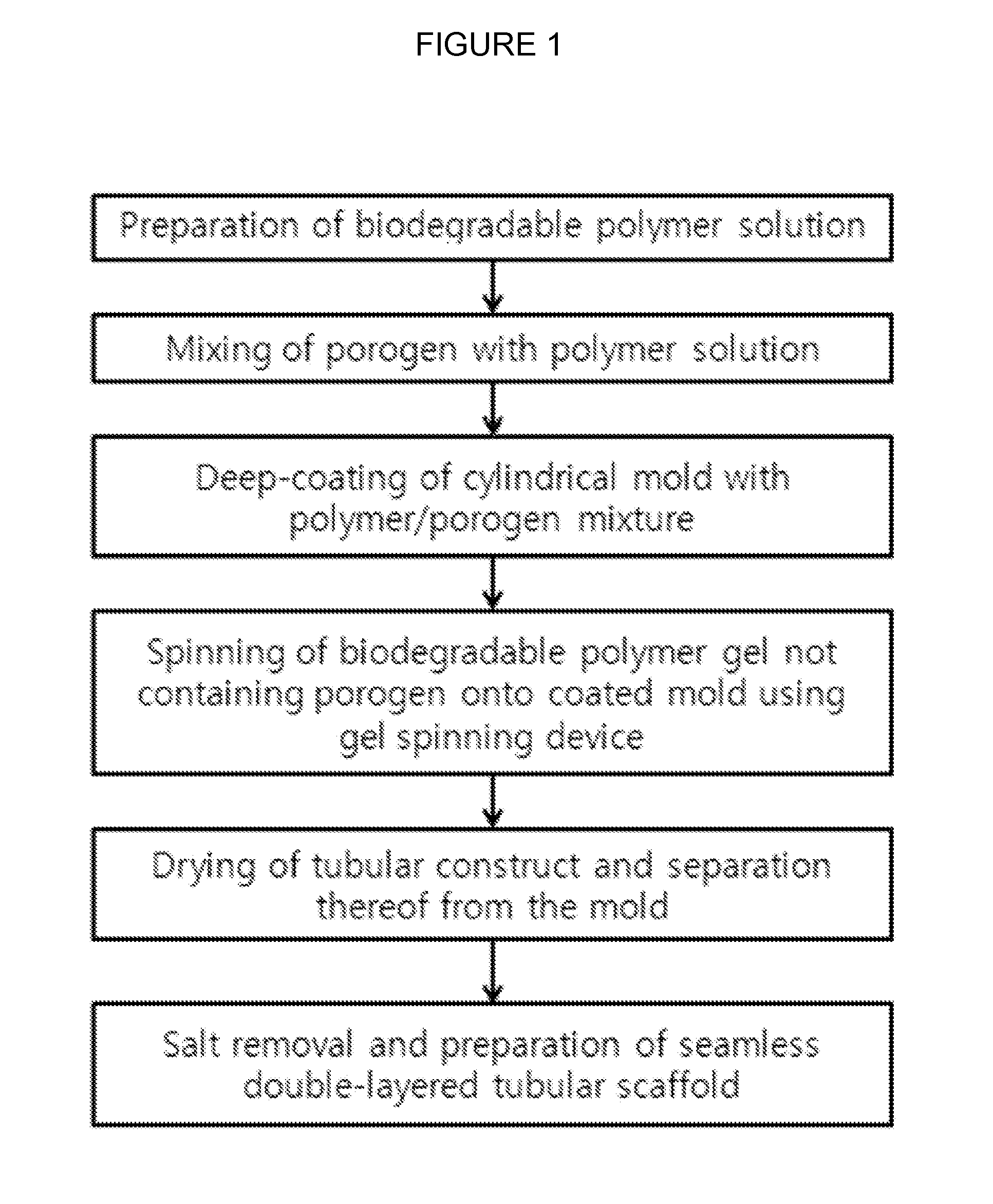
Preparation of Tube-Type Porous Scaffolds Having a Double-Layered Structure
[0039]PLCL (50:50 composition ratio of monomers) having a molecular weight of 450,000 Da was dissolved in chloroform at a concentration of 7.0% (w/v). Sodium chloride less than 20 microns in diameter was separated through sieving, and was mixed with the PLCL solution at PLCL to NaCl ratios of 1:1, 2:1 and 9:1. A cylindrical shaft 6.5 mm in diameter was immersed in the PLCL/NaCl mixture to a depth of about 10 cm, and was impregnated at 25° C. for 15 min, thereby forming an inner porous coating layer containing micropores on the surface of the cylindrical shaft.
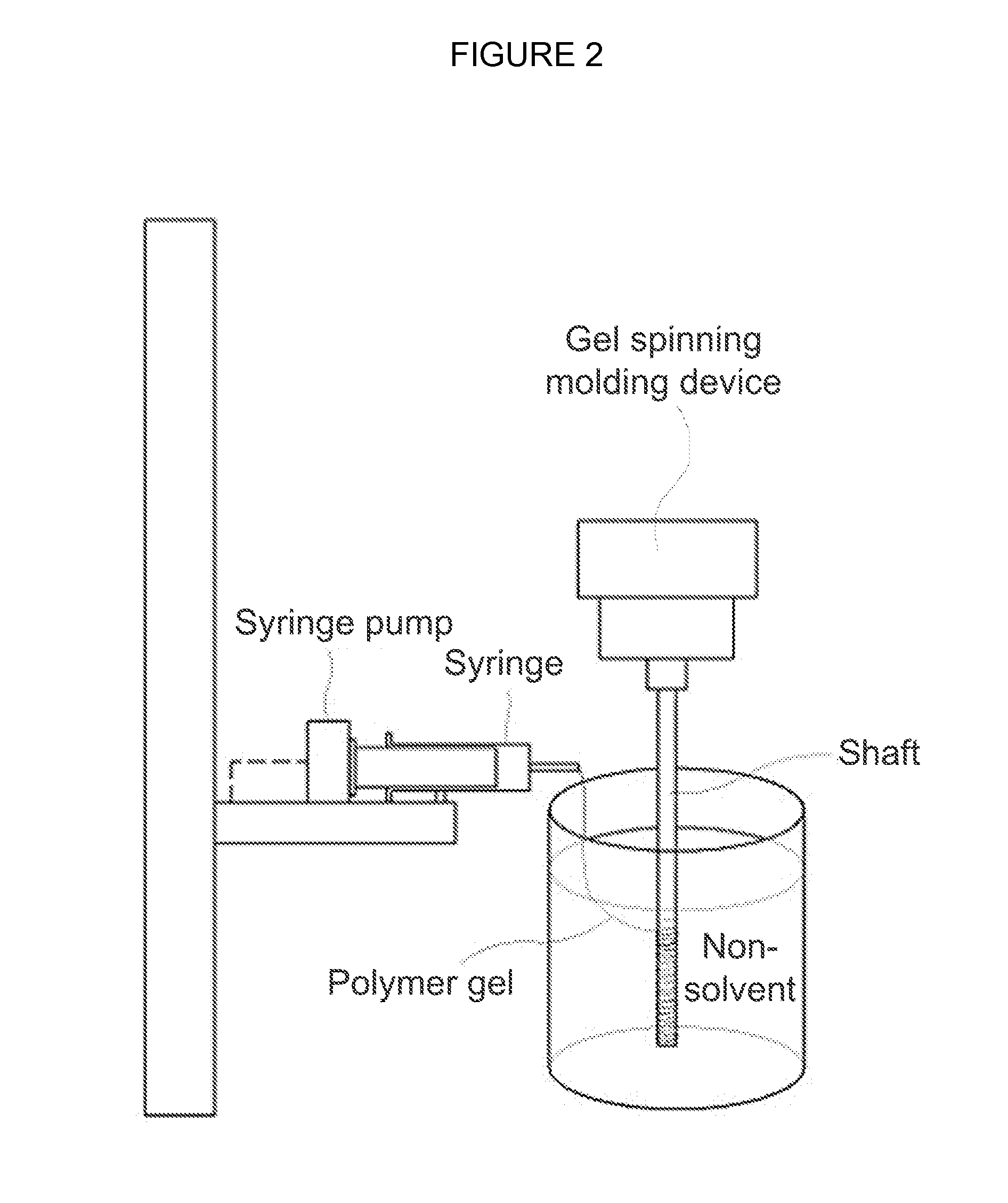
[0040]The cylindrical shaft having the inner porous coating layer was immersed in a coagulation bath containing methanol and rotated at 300 rpm. PLCL, having the same molecular weight as that used for forming the inner layer, was dissolved in chloroform at a concentration of 7.5% (w/v), poured into a syringe of a gel spinning device, and spun down through the syringe using a syringe pump into the coagulation bath. The spun biodegradable polymer gel underwent phase separation into gel-phase polymer fibers. The gel-phase polymer fibers were allowed to wind around the inner porous coating layer of the cylindrical shaft rotating in the coagulation bath. At this time, the attachment between the inner porous coating layer and the outer polymer fibrous layer was induced by the solvent remaining in the polymer fibrous gel, which was wound around the inner layer, thereby fabricating a porous scaffold having a double-layered structure. Then, the cylindrical shaft was dried in a vacuum dryer to separate the double-layered porous scaffold from the shaft.
[0041]FIG. 1 is a schematic diagram showing the preparation of a tube-type porous scaffold having a double-layered structure for use as an artificial vascular graft according to the above procedure. FIG. 2 is a schematic representation of a gel spinning device for spinning a biodegradable polymer gel into a non-solvent coagulation bath according to the present invention.
[0042]The porous scaffold prepared according to the above procedure had a double-layered tubular structure. The inner porous coating layer and the outer polymer fibrous layer were attached to each other and had different pore sizes. In detail, the tube-type porous scaffold had an inner diameter of 6.5 mm and a thickness of 1.0 mm. The fibers, constituting the outer layer of the scaffold, were individually 30 to 100 microns in diameter. Also, the inner porous coating layer had a pore size of 15 microns, and the outer polymer fibrous layer had a pore size ranging from 50 to 150 microns. Further, the porosity of the inner and outer layers, which was measured using a mercury injection pore measuring instrument, was found to be greater than 60%. When the scaffold was stretched to 400% of its original length, it returned to more than 98% of its original length.
[0043]The porous scaffold was observed under a scanning electron microscope (SEM). The outer surface of the porous PLCL scaffold was found to have a fibrous structure (FIG. 3a). The inner surface of the PLCL scaffold contained few pores (FIG. 3c). A cross-sectional SEM micrograph of the porous PLCL scaffold revealed that the outer gel-phase polymer fibrous layer and the inner porous coating layer were properly attached to each other, and that the outer layer was highly interconnected between pores.

Example

Comparative Example 1
Preparation of a Single-Layered Porous Scaffold
[0044]A single-layered porous scaffold was fabricated by gel spinning a highly viscous PLCL solution onto a rotating cylindrical shaft according to the same method as in Example 1, except that the cylindrical shaft was coated with the PLCL solution instead of the PLCL/NaCl mixture. The cross section and inner surface of the single-layered porous scaffold thus obtained were observed under a scanning electron microscope, and are shown in FIGS. 4a and 4b, respectively.

Example

Test Example 1
Evaluation of Burst Strength and Blood Leakage
[0045]The double-layered porous scaffolds prepared in Example 1 were evaluated to estimate the burst strength thereof and the leakage of blood therefrom. A predetermined amount of human blood was put into a tube, which was connected to the porous scaffolds. Then, pneumatic pressure was slowly applied to the tube up to 1500 mmHg. During the pressure application, the pressure at which the scaffold was deformed and the blood leaked from the scaffold was recorded. The results are given in Table 1, below. The single-layered porous scaffold prepared in Comparative Example 1 was used as a comparative group.
TABLE 1 Burst pressure Leakage pressure (mmHg) (mmHg) Single-layered scaffold — 30 Double-layered scaffold 1500 1500 (PLCL/NaCl, 9:1) Double-layered scaffold 1200 1200 (PLCL/NaCl, 2:1) Double-layered scaffold 1200 1200 (PLCL/NaCl, 1:1)
[0046]As shown in Table 1, in the case of the single-layered porous scaffold of Comparative Example 1, which did not have an inner porous coating layer, the blood leakage occurred at lower than 30 mmHg, and the burst pressure could not be measured because the burst pressure was lower than 30 mmHg. In contrast, the porous scaffold having a double-layered structure comprising an inner porous coating layer and an outer polymer coating layer, prepared in Example 1 according to the present method, did not exhibit deformation or leakage even at 1200 mmHg. In particular, the double-layered scaffold constructed at a PLCL to NaCl ratio of 9:1 did not burst even at higher than 1500 mmHg.

PUM

PropertyMeasurementUnit
Fraction0.01fraction
Fraction0.2fraction
Pore size40.0μm
tensileMPa
Particle sizePa
strength10

Description & Claims & Application Information

We can also present the details of the Description, Claims and Application information to help users get a comprehensive understanding of the technical details of the patent, such as background art, summary of invention, brief description of drawings, description of embodiments, and other original content. On the other hand, users can also determine the specific scope of protection of the technology through the list of claims; as well as understand the changes in the life cycle of the technology with the presentation of the patent timeline. Login to view more.

Similar technology patents

Classification and recommendation of technical efficacy words

Why Eureka
Try Eureka