

Method and apparatus for manufacturing porous articles
a technology of porous articles and manufacturing methods, applied in additive manufacturing, molten spray coating, coatings, etc., can solve the problems of high melting point, additional difficulties, and limited control of the size and distribution of the pores, and achieve the effect of high melting poin
- Summary
- Abstract
- Description
- Claims
- Application Information
AI Technical Summary
Benefits of technology
Problems solved by technology
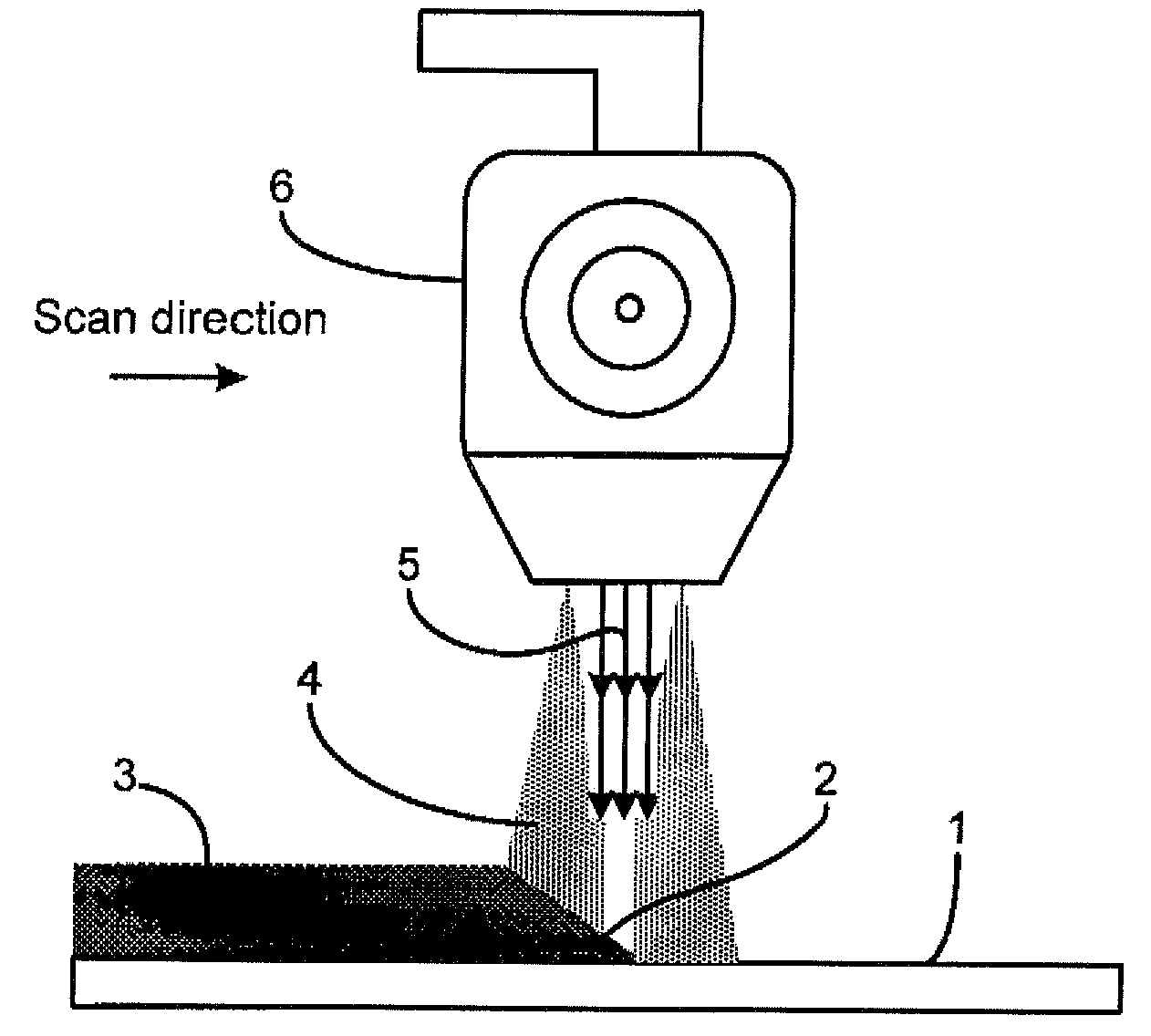
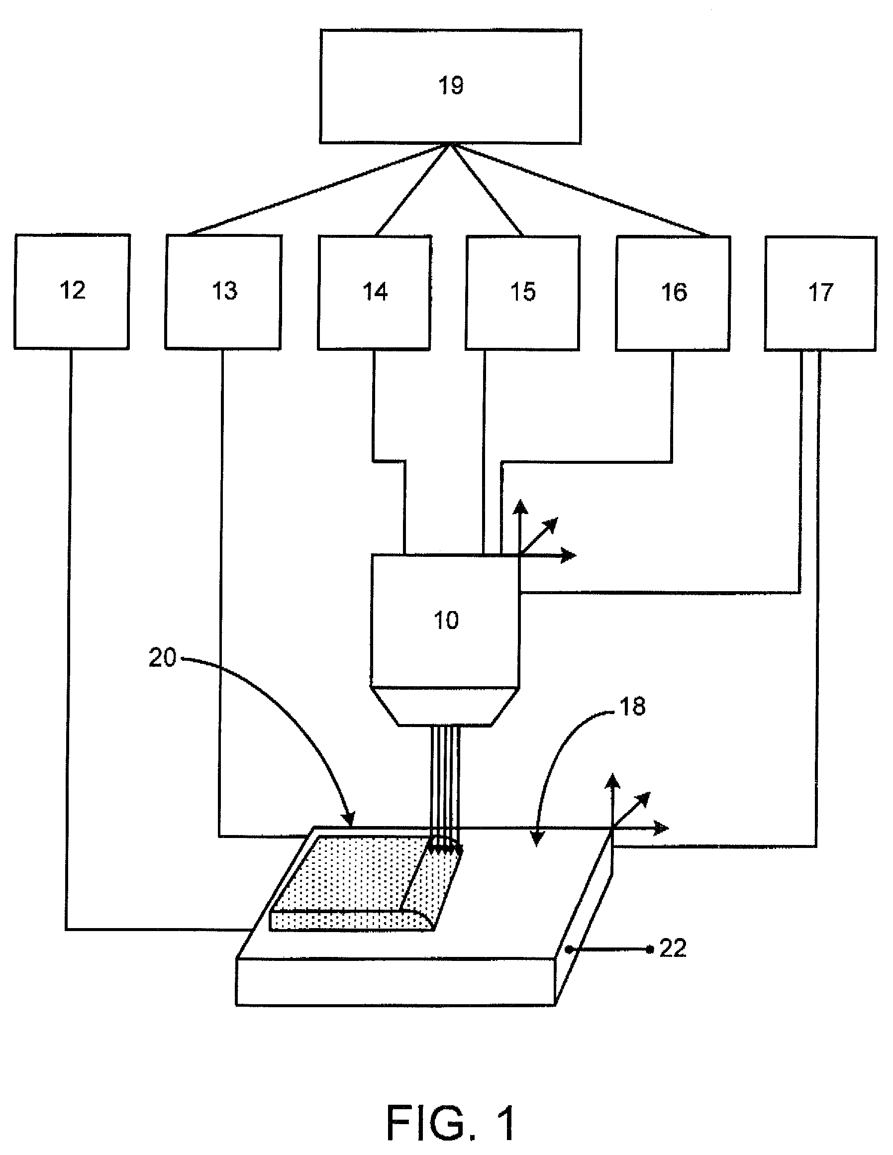
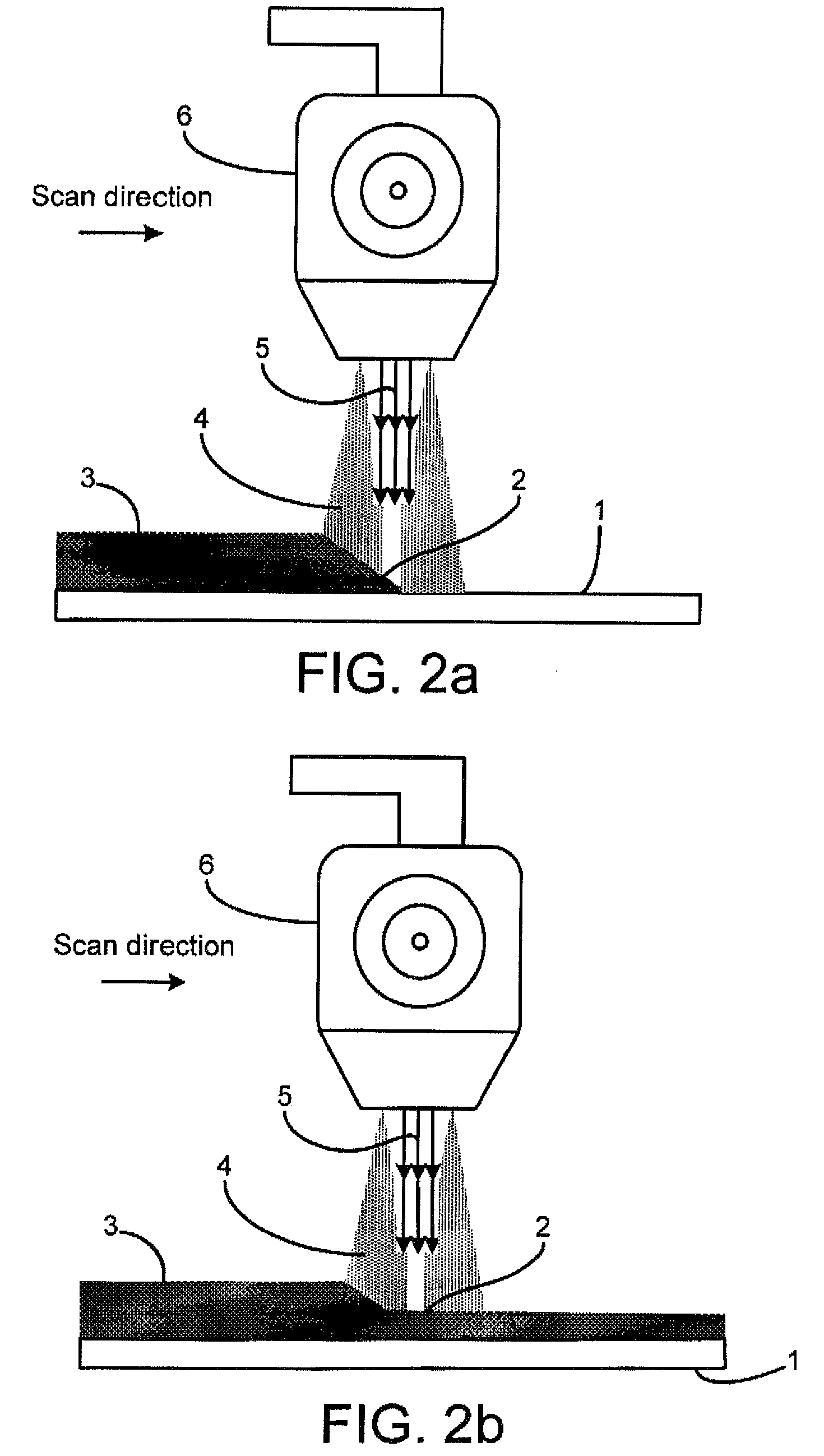
Method used
Image

Examples
examples 1
Titanium Foam Bar Produced From Powder
[0142]In this example we use Ti powder having particle size ranging from 10 to 2000 micron average size. Smaller particles give smaller pore size in the final product. In this particular example, particles 50-100 microns average size were used.
[0143]Pure argon was used as the shield gas and plasma gas.
[0144]A graphite plate or shaped graphite mandrel having the shape desired in the porous article is used as the substrate.
[0145]Programming: torch liner motion speed (7 inch (17.78 cm) per minute); torch oscillation parameters (amplitude—1 inch—(2.54 cm)—; period—2 seconds, and dwell in the extreme points 0.01 and 0.01 second); plasma power (current—70 Amps and voltage—30 V); torch motion trajectory—3 inches (7.62 cm) liner reciprocal; powder feed rate—1.7 (0.77 kg) pound per hour; number of layers—50.
[0146]Every layer can be programmed in individual parameters (if it is desired). So in this way layer by layer a porous rectangular body is formed th...
example 2
Titanium Foam Tube Produced From Wire
[0147]In this example a wire 0.04″ (0.10 cm) diameter was used.
[0148]Pure argon was used as the shield gas and plasma gas.
[0149]A graphite disc was used as the substrate.
[0150]Programming: torch liner motion speed (10 inch (2.54 cm) per minute); torch oscillation parameters (amplitude—1 inch (2.54 cm), period—2 seconds, and dwell in the extreme points 0.01 and 0.01 second); plasma power (current—77 Amps and voltage—30 V); there was no torch motion trajectory; substrate rotation speed was 0.5 revs per minute; torch distance from center of rotation was 2 inches (5.04 cm); plane of substrate rotation was horizontal; powder feed rate was 2 pounds per hour (0.90 kg); number of revs—80. So in this way rev by rev the porous tubular body is formed with an inner diameter of 1.5 inch (3.81 cm), and an outer diameter of 2.5 inch (6.35 cm) with a porosity—47%, and average pore size of 65 microns.
example 3
Titanium Solid-Porous-Solid Bar Produced From Powder
[0151]In this case, particles 50-100 microns average size was used.
[0152]Pure argon was used as shield gas and plasma gas.
[0153]A graphite plate was used as the substrate.
[0154]Programming: torch liner motion speed (7 inch (17.78 cm)per minute); torch oscillation parameters (amplitude—1 inch (2.54 cm), period—2 seconds, and dwell in the extreme points 0.01 and 0.01 second); plasma power: first 10 layers—100 Amps; then next 30 layers 70 Amps, then next 15 layers 100 Amps; torch motion trajectory—3 inches (7.62 cm) liner reciprocal; powder feed rate—2.2 pounds (1 kg) per hour; number of layers—55.
[0155]A layered solid-porous-solid bar is formed that has a length 3 inches (7.62 cm), width 1 inch (2.54 cm), and height—1.7 inches (4.32 cm). The first layer is solid with a thickness of 0.2″ (0.51 cm), the porous layer thickness was 1.2″ (3.05 cm), and the second solid layer thickness was 0.3″ (0.76 cm). The porosity of the porous layer w...
PUM
| Property | Measurement | Unit |
|---|---|---|
| melting temperature | aaaaa | aaaaa |
| particle size | aaaaa | aaaaa |
| size | aaaaa | aaaaa |
Abstract
Description
Claims
Application Information