
Novel synergistic process and recipe for fabrication of a high integrity membrane electrode assembly of solid oxide fuel cell

a fuel cell and membrane electrode technology, applied in the direction of cell components, final product manufacturing, sustainable manufacturing/processing, etc., can solve the problems of low reliability and yield of cell stacks, and achieve high integrity, high integrity, and high mechanical strength.

Active Publication Date: 2009-03-12
INST NUCLEAR ENERGY RES ROCAEC
View PDF20 Cites 21 Cited by
  • Summary
  • Abstract
  • Description
  • Claims
  • Application Information

AI Technical Summary

Benefits of technology

[0009]The main objective for the invention is to provide a material recipe and its process to produce HI-SOFC-MEA or HI-Unit Cell. Such a HI-SOFC-MEA has ① high mechanical strength and hardness ② adjustable substrate porosity and gas permeability ③ controllable MEA multi-layer materials and microstructure or density ④ controllable MEA layer number and thickness ⑤ high sintering density ⑥ high stability and robust operational capability. Due to the above special characteristics, the HI-SOFC-MEA can increase cell output powder density and fuel energy conversion efficiency. The most important feature is its high mechanical strength that is suitable for Cell Stack assembly and test. Cells with fragility tend to cause rupture or lower reliability and yield for cell stacks during production or testing process.
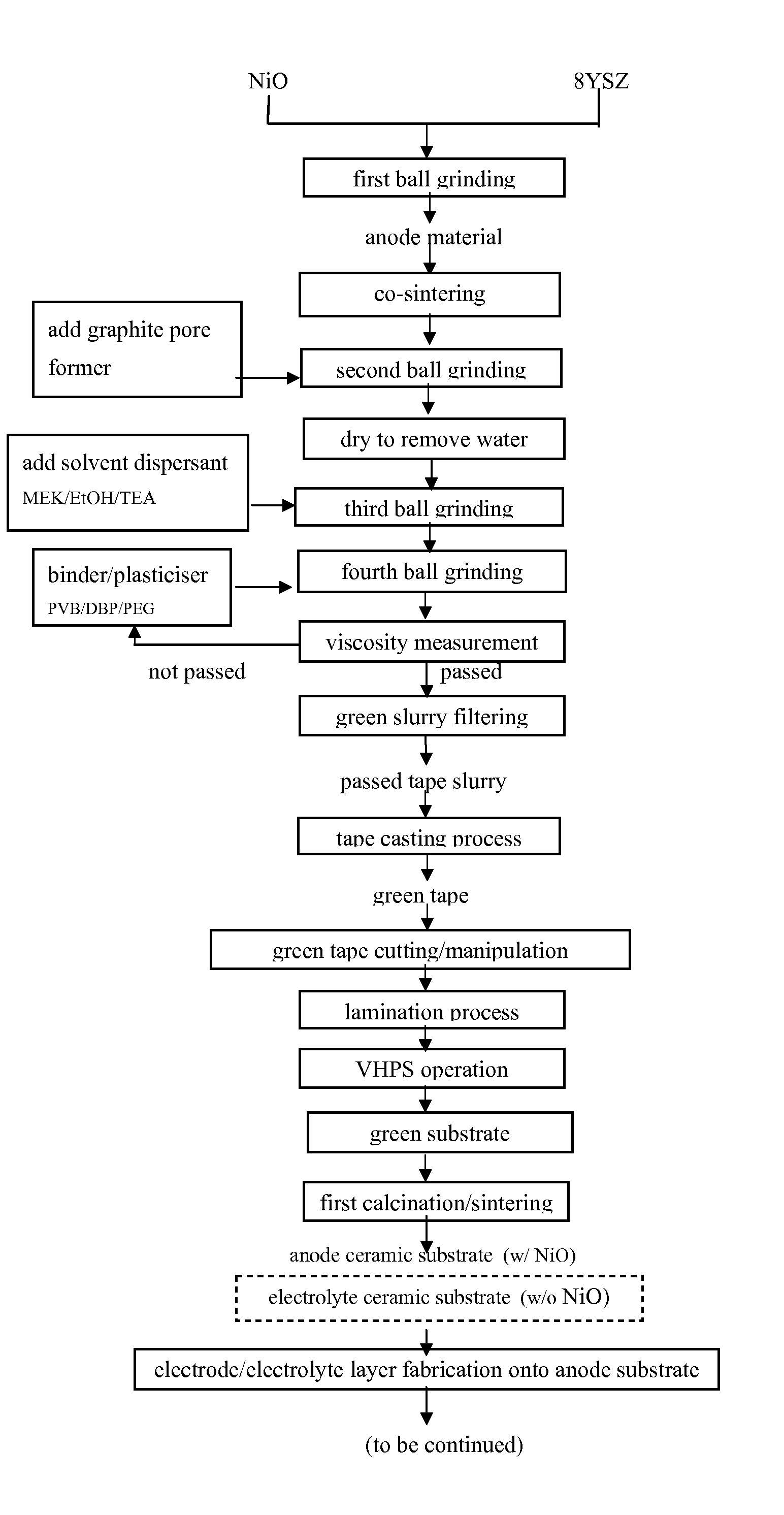
[0015]For electrolyte substrate / layer recipe, its optimum composition in weight percentage is: 8 YSZ (68 wt %), MEK (17 wt %), EtOH (7 wt %), TEA (1.5 wt %), DBP (1.0 wt %), PEG (1.0 wt %), PVB (4.5 wt %) and pore former (0. wt %). Since the electrolyte layer requires “zero gas permeability and 100% tightness”, there is no need of pore former. For anode substrate / layer recipe, the optimum composition is: NiO+8YSZ (68 wt %) (NiO / 8YSZ has weight ratio 50 / 50 (approximately optimum value)), MEK (17 wt %), EtOH (7 wt %), TEA (1.5 wt %), DBP (1.0 wt %), PEG (1.0 wt %), PVB (4.5 wt %), pore former (graphite) (0.1˜10 wt % of anode material). The amount of pore formers can be adjusted according to the porosity required by anode substrate. The weight percentage in Table 1 can be adjusted according to the powder characteristics of the electrode materials (pore diameter distribution and specific surface area et al.). The goal is to produce high uniformity and high quality green products with suitable operation parameters for tape casting (such as thickness / density / operational feasibility). The electrode materials and pore formers in the recipe need pretreatment. The primary process is to grind the electrode powder materials down to 200˜300 nm by a ball mill (containing zirconium dioxide). Then, the powder materials, organic solvents and dispersants are ground together inside the ball mill for about 24˜48 hours (adjustable to reduce grinding time) to attain uniformity. At last, plasticizers and binders are added to the ball mill for grinding for another 24˜48 hours (adjustable to reduce grinding time) to attain complete uniformity and slurry. To attain the required green thickness, it is necessary to do fine adjustment of recipe and carryout viscosity measurement and adjustment. If the green thickness is 10˜200 μm, the slurry viscosity is 100˜1500 cp (depending on the original powder characteristics; experience and techniques are essential to process optimization), so the optimal viscosity will facilitate tape casting operation.
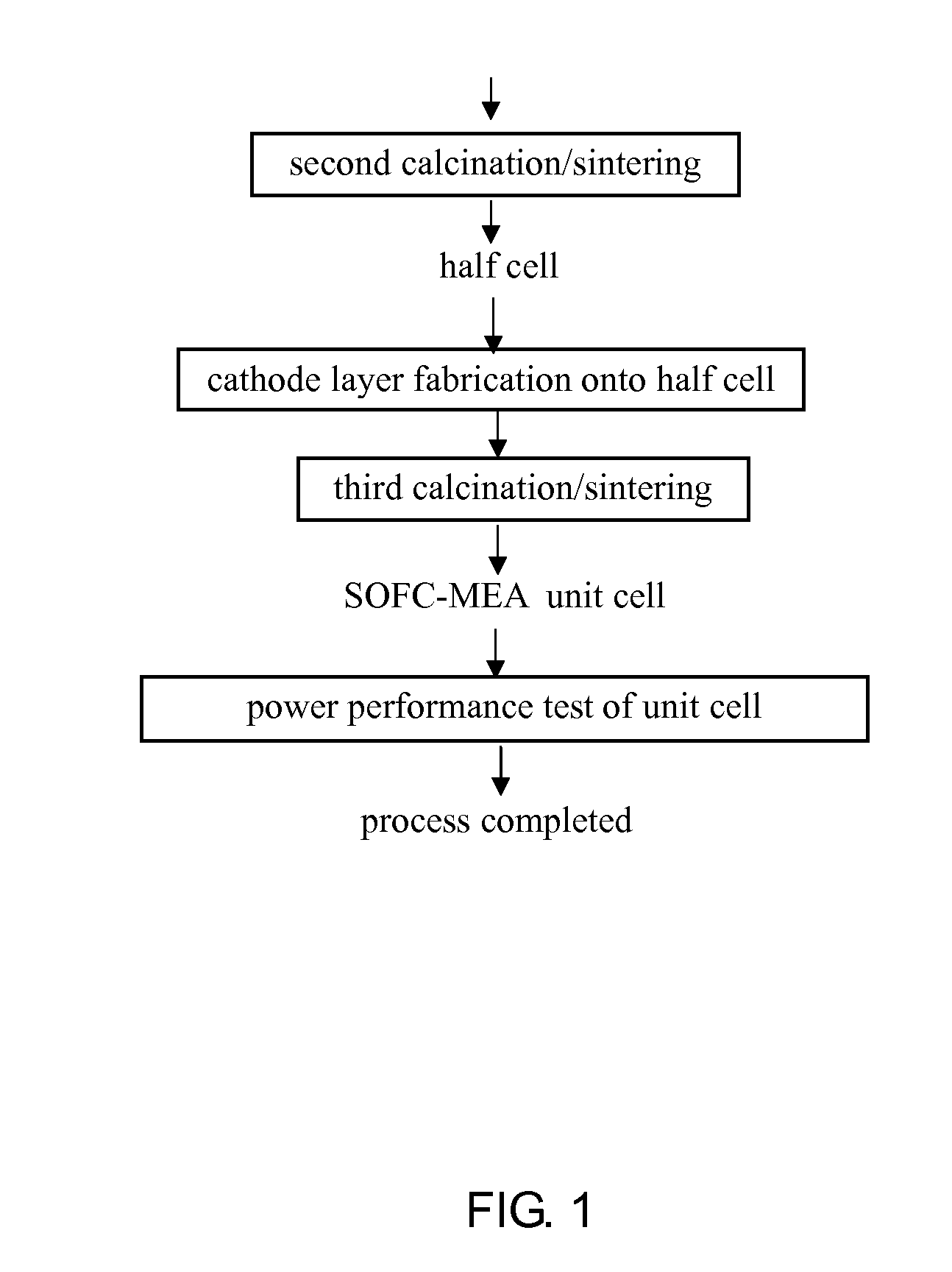
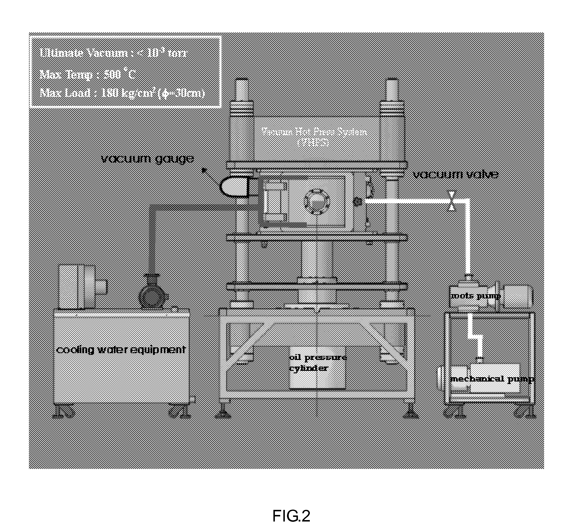
[0018]The green tape produced from previous (1) process is made into a single layer green product in certain size by punching / blanking. Then a number of green products are selected to go through inspection, stacking and Lamination Process (LP) to produce electrode green substrate-A with definite thickness and shape. The lamination process has temperature at 60˜100° C. and pressure at 2000 psi˜5000 psi. At this time, the green substrate-A density is 40% of the theoretical density for the same ceramic oxides as the electrode materials. The green substrate-A will go to the second stage VHPS to produce green substrate-B. The process vacuum is 10−3˜10−4 torrs and pressure is 1.68×10⁵ psi (area=9 cm2)˜1.52×10⁴ psi (area=100 cm2), and temperature is 500° C. The density for this green substrate-B can reach 70% of the theoretical density for the same ceramic oxides as the electrode materials. Such two-stage vacuum heat lamination process is defined as Novel Synergistic Process (NSP). During LP stage, the green is placed freely on the pressboard. While during VHPS stage, the green is sealed and placed in the mold with definite size. The electrode green substrate through NSP process has high integrity. After calcinations / sintering, the electrode ceramic substrate has high integrity and extremely high mechanical strength. Further through other treatments or processes for other electrode layers (like cathode or electrolyte), such as screen-printing, sputtering coating, plasma coating / spraying, spin coating et al., the unit cell is produced with unique properties, including high mechanical strength (suitable for cell stack assembly and testing), high durability and stability. This is called “high integrity fuel cell membrane electrode assembly”. By changing the amount of pore former, it is possible to adjust the content and microstructure for the anode substrate to vary the porosity between different layers, to increase gas permeability rate, to increase cell energy conversion efficiency and output powder density. Thus, the key technology to produce SOFC-MEA is developed to improve the product specification requirements and performance.

Problems solved by technology

Cells with fragility tend to cause rupture or lower reliability and yield for cell stacks during production or testing process.

Method used


Image

  • Novel synergistic process and recipe for fabrication of a high integrity membrane electrode assembly of solid oxide fuel cell
  • Novel synergistic process and recipe for fabrication of a high integrity membrane electrode assembly of solid oxide fuel cell
  • Novel synergistic process and recipe for fabrication of a high integrity membrane electrode assembly of solid oxide fuel cell

Examples


example 1

Production of SOFC Anode Substrate and Unit Cell with High Mechanical Strength and Suitable Porosity (20˜30 vol %)

[0046]The example is about production of a planar SOFC anode substrate with high mechanical strength and suitable porosity (20˜30 vol %) and its unit cell for powder supply test and powder generation. The production includes two stages. The first stage is about (1) NiO+YSZ anode green substrate slurry recipe and processes, including 8 steps in total, and (2) anode ceramic substrate production process, 5 steps in total, which are described respectively in the following:

[0047](1) NiO+8YSZ anode green substrate slurry recipe and processes consist of the following steps (as shown in FIG. 4):

[0048]Step 1: Mix 175 grams of 8YSZ with cubic crystal structure and equal amount of NiO (average particle diameter 1000 nm) and place them in a jar containing ZrO2 grinding balls (about 250 grams) for 168 hours of grinding. This allows complete mixing of NiO and 8YSZ to become highly uni...


PUM

PropertyMeasurementUnit
Temperatureaaaaaaaaaa

Abstract

A recipe and two sequential processes for fabrication of electrode substrates of solid oxide fuel cells (SOFCs) are described in this invention. The typical recipe consists of 50˜86 wt % electrolyte (8YSZ) or 50˜80 wt % anode electrode (NiO / 8YSZ), 12˜22 wt % MEK (solvent 1), 5˜9 wt % EtOH (solvent 2), 1˜2 wt % TEA (dispersant), 0.5˜2 wt % DBP (plasticizer 1), 0.5˜2 wt % PEG (plasticizer 2), 3˜6 wt % PVB (binder), and 0.1˜10 wt % graphite (pore former). Two sequential processes include: 1. The process for preparation of the green tape slurry from materials of the recipe, 2. The synergistic process for fabrication of a high integrity membrane electrode assembly (MEA) of SOFC from the prepared electrode substrates.

Description

BACKGROUND OF THE INVENTION[0001]1. Field of the Invention[0002]The invention is related to an innovative process for membrane electrode assembly, from formulating with raw materials, and preparing electrodes of planar SOFC-MEA containing anode and electrolyte substrate slurry, to making green tape of electrode by tape casting process. The green tape is cast into green substrate by lamination process, and then finished into high integrity green substrate by vacuum hot press system (VHPS). Through calcinations and sintering, the green substrate can be made into electrode substrate with high mechanical strength, controllable micro-structural characteristics (porosity / gas permeability), thickness, and dimensions. Further, screen-printing, sputtering coating, spin coating, and spraying processes are alternatively employed to enable the production of high-performance SOFC unit cell. Their application to SOFC assures high reliability, durability and low degradation rate of the unit cell. ...

Claims


Application Information

Patent Timeline
IPC IPC(8): C23C4/10
CPCH01M4/8885H01M4/9066H01M8/1226Y02E60/525H01M2008/1293Y02E60/521H01M8/1246Y02E60/50Y02P70/50
Inventor LEE, MAW-CHWAINKAO, WEI-XINLIN, TAI-NANCHANG, YANG-CHUANGWANG, CHUN-HSIU
Owner INST NUCLEAR ENERGY RES ROCAEC
Learn More