

Continious production of exfoliated graphite composite compositions and flow field plates
a technology of exfoliated graphite and composite composition, which is applied in the field of continuous production of composite compositions, can solve the problems of significant impact on the performance, durability, cost, and cost of the fuel cell system, and achieve the effect of reducing the size of the fuel cell stack and high areal conductivity
- Summary
- Abstract
- Description
- Claims
- Application Information
AI Technical Summary
Benefits of technology
Problems solved by technology
Method used
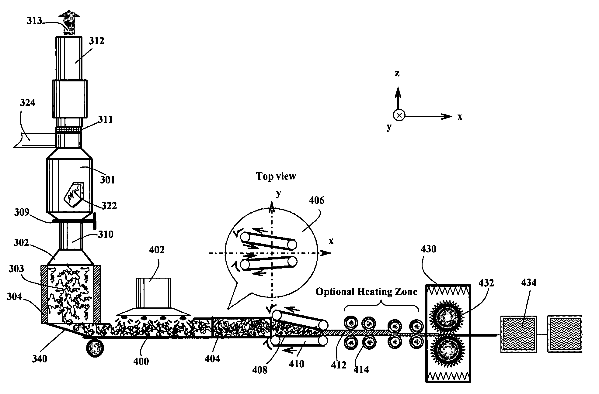
Image

Examples
example 1
Polyethylene-Expanded Graphite Composites
[0077]A series of composite compacts were prepared as follows:
[0078]Sample 1-A: Ultrafine polyethylene (PE) powder, having an average particle size of about 10 μm, was dry-blended with 30% by weight of non-expandable natural graphite particles and 70% by weight of acid-intercalated, expandable graphite (based on the total weight of expandable and non-expandable graphite). The PE amounts were 5, 15, 25, and 50% by weight based on the total weight of the resulting composite composition. The non-expandable graphite was intended for use as an isotropy-promoting agent. The three-component mixture was transported through a quartz tube, which was set at a temperature of 1,100° C. and the residence time of graphite in the heated zone was approximately for 20 seconds. Rapid expansion or exfoliation of the expandable graphite occurred and, surprisingly, the PE did not suffer any significant thermal degradation as would have been expected by polymer sci...
example 2
Polyethylene-Expanded Graphite Composites (Bi-Axial and Triaxial Compression)
[0085]Sample 2-A is identical to sample 1-A (15% PE) and Sample 2-D is identical to sample 1-D. However, Samples 2-A and 2-D were subjected to bi-axial compression (the first compression vector is defined as the X-axis direction and the second compression vector is the Y-axis direction) at a final pressure of 500 psi and, separately, tri-axial compression (samples compressed in X- and Y-axis directions first, followed by a final Z-axis compression (12,500 psi) to form a thin plate). The samples were consolidated (heated to above 160° C.) and then cooled under a final pressure of 500 psi (sample of biaxial compressions only) and 12,500 psi (triaxial compression sample), respectively. The electrical conductivity values in the three directions of all samples are given in Table 2:
TABLE 2Electrical conductivity of biaxial and triaxial compression samples.X-axisY-axisCompressionconduc.,conduc.,Z-axis conduc.,Samp...
example 4
Thermoset Resin-Expanded Graphite Composites
[0088]Sample 4-A: First, 30% by weight of non-expandable natural graphite particles and 70% by weight of bromine-intercalated, expandable graphite (based on the total weight of expandable and non-expandable graphite) were dried blended. The non-expandable graphite was intended as an isotropy-promoting agent. The mixture was enclosed in a quartz tube, which was purged with nitrogen gas and then sealed from both ends of the tube with ceramic cloth. The tube was rapidly transferred to the center of a tube furnace pre-heated to a temperature of 600° C. and maintained at that position for 30 seconds. Rapid expansion or exfoliation of the expandable graphite occurred. The resulting graphite worms were then mixed with 25% by weight of fine phenol-formaldehyde powder, based on the total weight of the resulting composite composition. The resulting mixture was charged into a mold, heated to 200° C., and uniaxially compressed to a pressure of 15,000 ...
PUM
| Property | Measurement | Unit |
|---|---|---|
| pressure | aaaaa | aaaaa |
| pressure | aaaaa | aaaaa |
| pressure | aaaaa | aaaaa |
Abstract
Description
Claims
Application Information