Pitted metallic implants and method of manufacturing thereof

Inactive Publication Date: 2009-03-26
CHERKES DAVID
View PDF1 Cites 20 Cited by
  • Summary
  • Abstract
  • Description
  • Claims
  • Application Information

AI Technical Summary

Benefits of technology

[0023]It is a further aim of the invention to provide a low temperature, low pressure, simple manufacturing route with minimal processing steps for fabricating prosthetics with dimpled surfaces that are substantially free of brittle recrystallization zones and residual stresses.
[0024]It is a

Problems solved by technology

Such welded seams are potential failure regions and reduce the reliability of such stents.
Furthermore, the laser treatment tends to result in sharp edges.
These edges may be smoothed by electropolishing, but at best, this results in an additional processing step, which increases production costs and increases the risk of something going wrong, causing the component to be scrapped.
Thus welding, laser cutting and other high temperature processing technologies are inherently undesirable.
Invasive surgery risks infection and the site where metal is implanted into the body is prone to becoming infected.
The deposition and controlled release of active ingredients from the surface of metallic implants is not easy.
There is a problem with polymer coatings however, in that polymers are not fully biocompatible, and tend to degrade over time.
Since they are organic, they can serve as feedstocks for fungi and bacteria and thus are easily infected.
Even poly-methyl-methacrylate, though having a long history of use in surgery from the pioneering work by Chandler, is actually carcinogenic, wit

Method used


Image

  • Pitted metallic implants and method of manufacturing thereof
  • Pitted metallic implants and method of manufacturing thereof
  • Pitted metallic implants and method of manufacturing thereof

Examples


Embodiment Construction

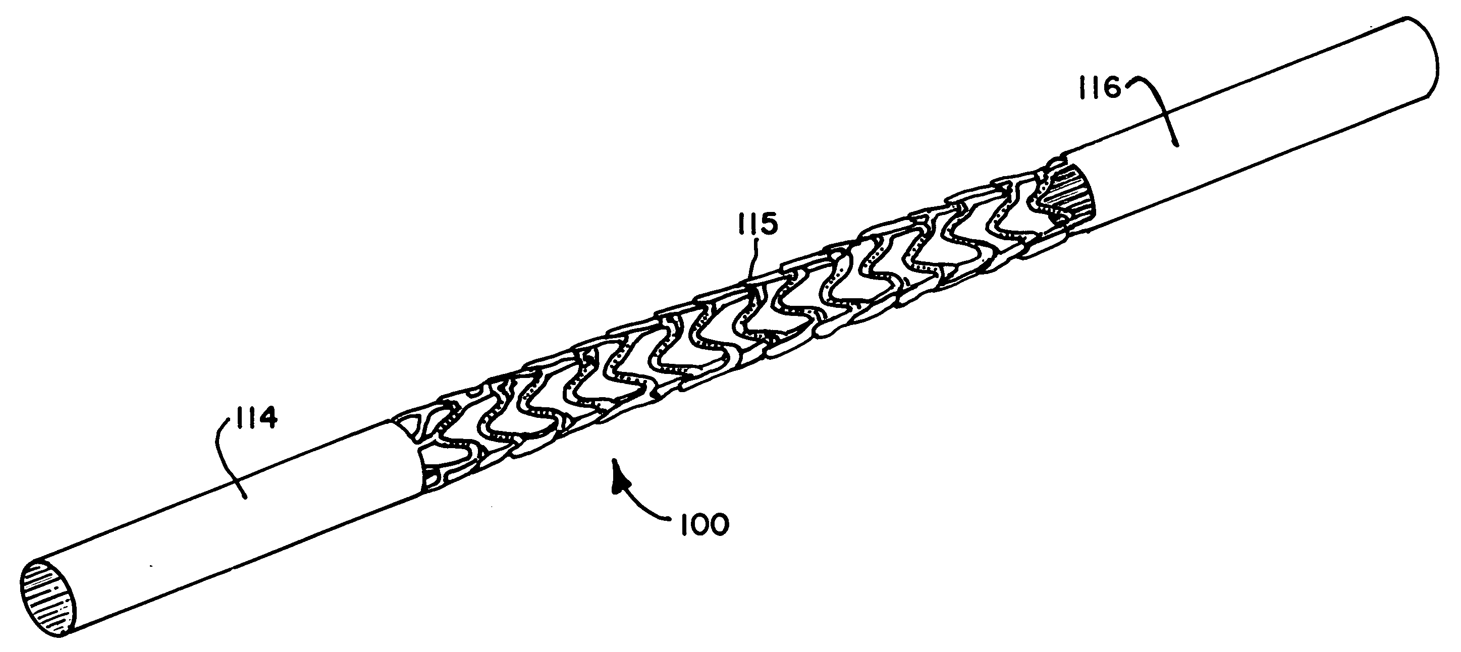
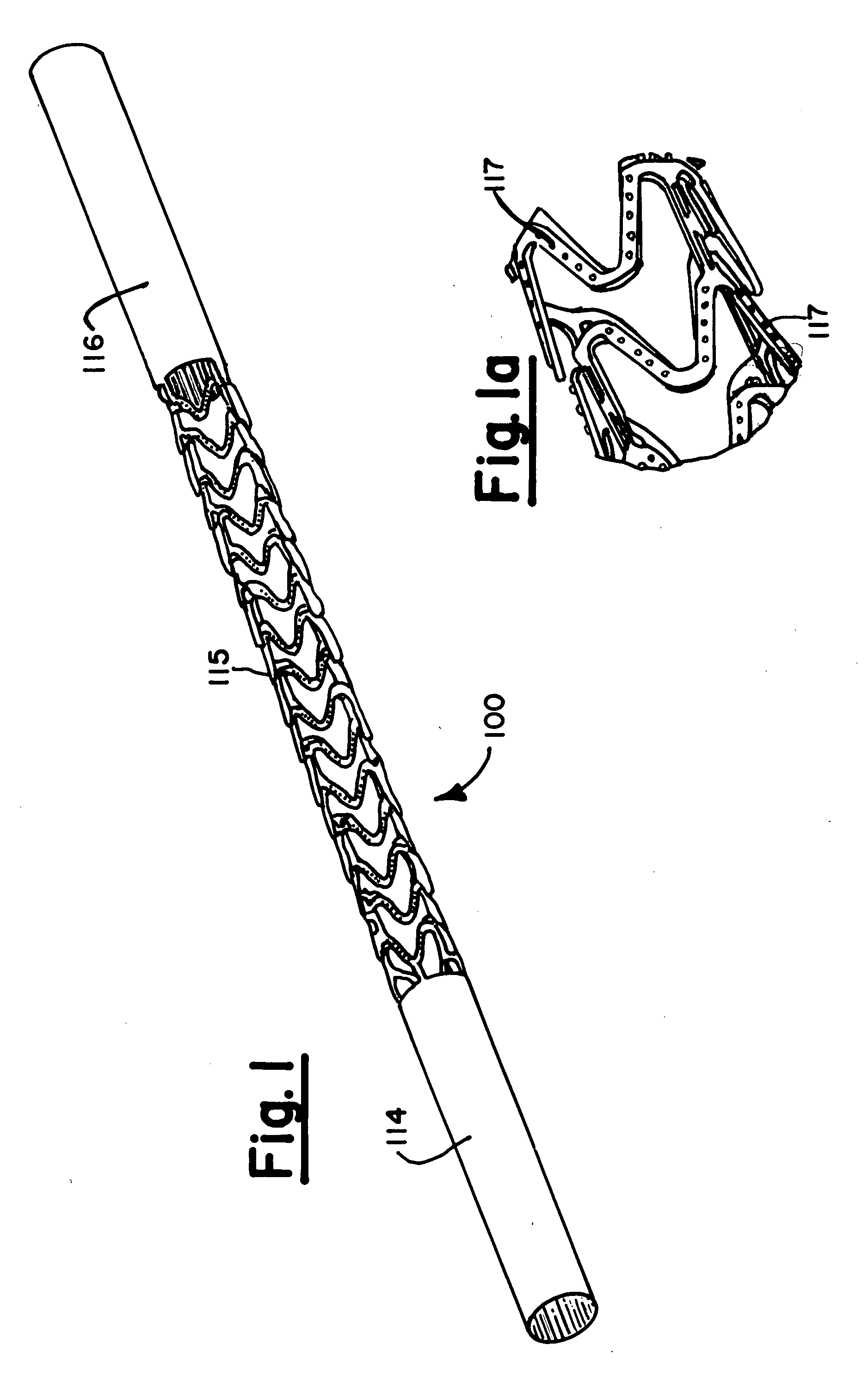
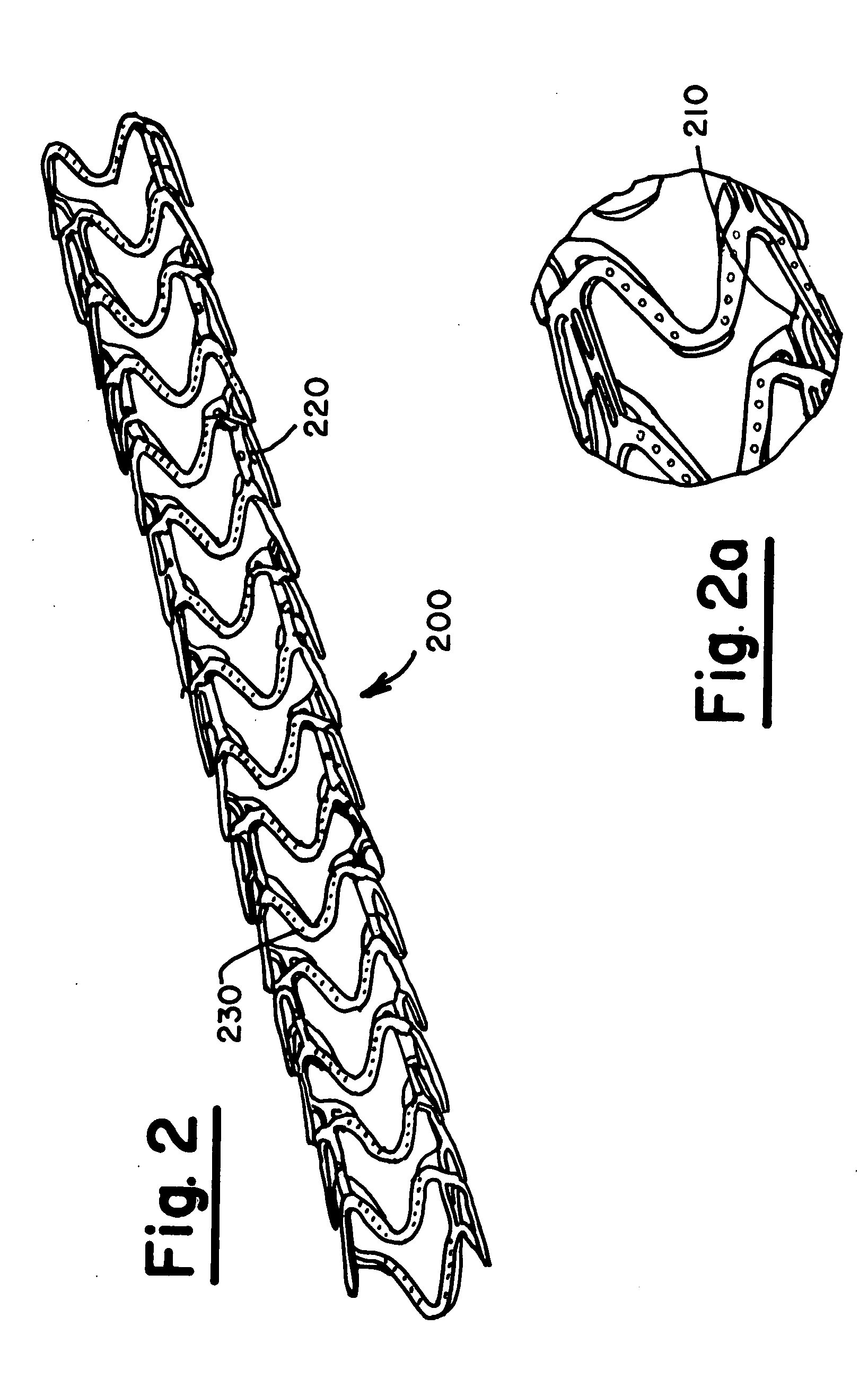
[0063]The present invention is directed to providing conductive components with micro-dimpled surfaces that are suitable for implantation within the human body, such as stents for example, and to methods of fabricating such components.

[0064]The conductive components are typically metallic and may comprise a metal, an alloy, graphite, a metallically conductive composite material and a conductive polymer.

[0065]The micro-dimpled surface of the components includes a number of recesses that serve as micro-reservoirs for bioactive materials, such as polymeric matrices impregnated with pharmaceutical compositions such as blood clotting agents, blood thinning agents, antibiotics, fungicides and / or chemotherapeutic compositions.

[0066]The recesses of micro-dimpled components of embodiments the invention may serve as reservoirs for drugs. Specific pharmaceuticals that have been successfully used in drug eluting cardiovascular stents include Rapamycin or Paclitaxel and the micro-dimpled surface...


PUM

PropertyMeasurementUnit
Temperatureaaaaaaaaaa
Electrical conductoraaaaaaaaaa
Bioactiveaaaaaaaaaa

Abstract

A method of fabricating a conductive prosthetic, such as a stent, with a dimpled surface comprising the steps of: (i) providing a blank; (ii) electrochemically eroding superfluous material to leave a structural skeleton, (iii) electropolishing, (iv) dimpling the surface of the structural skeleton by selectively electrochemically eroding recesses on the surface of the prosthetic and (v) impregnating the recesses with a bioactive material, and prosthetics such as stents with dimpled surfaces fabricated thereby.

Description

FIELD OF THE INVENTION[0001]The present invention is directed to Metallic implants in general, and to stents in particular, having pits in the surface thereof, particularly but not exclusively to serve as a reservoir for bioactive materials, such as pharmaceutical compositions and the like.BACKGROUND OF THE INVENTION[0002]There are a number of metals and alloys that are considered as being biocompatible and are used for the fabrication of implants that are used within the body and expected to function for long periods of time.[0003]In many applications it is beneficial for such implants to release bioactive materials to aid recovery of surrounding tissue or to reduce the likelihood of trauma and infection in the vicinity of the implant.[0004]One type of prosthetic is the stent. Stents are metal frameworks that are inserted into lumens of vessels and ducts such as arteries, veins, the intestinal tract, etc. and serve as vascular scaffolding. For example, cardiovascular stents are typ...

Claims


Application Information

Patent Timeline
IPC IPC(8): A61F2/06B23H3/00A61F2/82
CPCA61F2/82A61F2240/001C25F7/00B23H9/00C25F3/16A61F2250/0068
Inventor CHERKES, DAVID
Owner CHERKES DAVID
Why Eureka
Try Eureka