Multiterminal solid electrolytic capacitor

a solid electrolytic capacitor and multi-terminal technology, applied in the direction of fixed capacitor details, capacitors, electrical equipment, etc., can solve the problems of equipment errors, high-frequency noise, and speed of operation, so as to reduce the voltage drop that occurs when the capacitor supplies the load with a current, the effect of filtering out high-frequency nois

Inactive Publication Date: 2009-04-23
TOKIN CORP
View PDF1 Cites 27 Cited by
  • Summary
  • Abstract
  • Description
  • Claims
  • Application Information

AI Technical Summary

Benefits of technology

[0027]Since the anode leads are the portions of the valve metal pattern, which extends in the porous sintered body and bends at a plurality of locations so as to have a desired path length, the portions projecting out of the porous sintered body, S21 representing the transmission loss at high frequencies can be reduced and the effect of filtering out high-frequency noise can be improved.
[0028]According to an embodiment of the present invention, a decoupling circuit is configured using a capacitor in which the inductance of a path extending from one of mounting terminals to a porous sintered body through one of anode leads is different from the inductance of a path extending from another one of the mounting terminals to the porous sintered body through another one of anode leads. One of the mounting terminals that is connected to one of the paths that has a lower inductance is connected to a load. One of the mounting terminals that is connected to one of the paths that has a higher inductance is connected to a power supply. Therefore, the voltage drop that occurs when the capacitor supplies the load with a current can be reduced.

Problems solved by technology

The performance increase of recent electronic devices increases the operation speed of semiconductor devices and the like; hence, high-frequency noise tends to occur.
High-frequency noise causes problems such as equipment errors and howls and therefore is filtered out with decoupling circuits.
Furthermore, measures need to be taken against the increase in equipment power consumption and sharp current fluctuations due to sharp load changes.

Method used


Image

  • Multiterminal solid electrolytic capacitor
  • Multiterminal solid electrolytic capacitor
  • Multiterminal solid electrolytic capacitor

Examples


example 1

[0056]A sample with outer dimensions of 3.5 mm×2.8 mm×1.9 mm was prepared in this example.

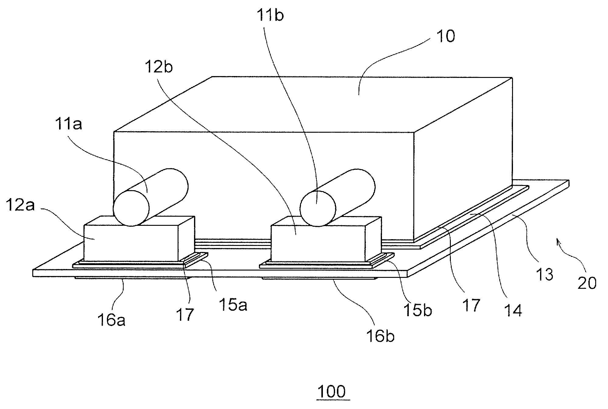
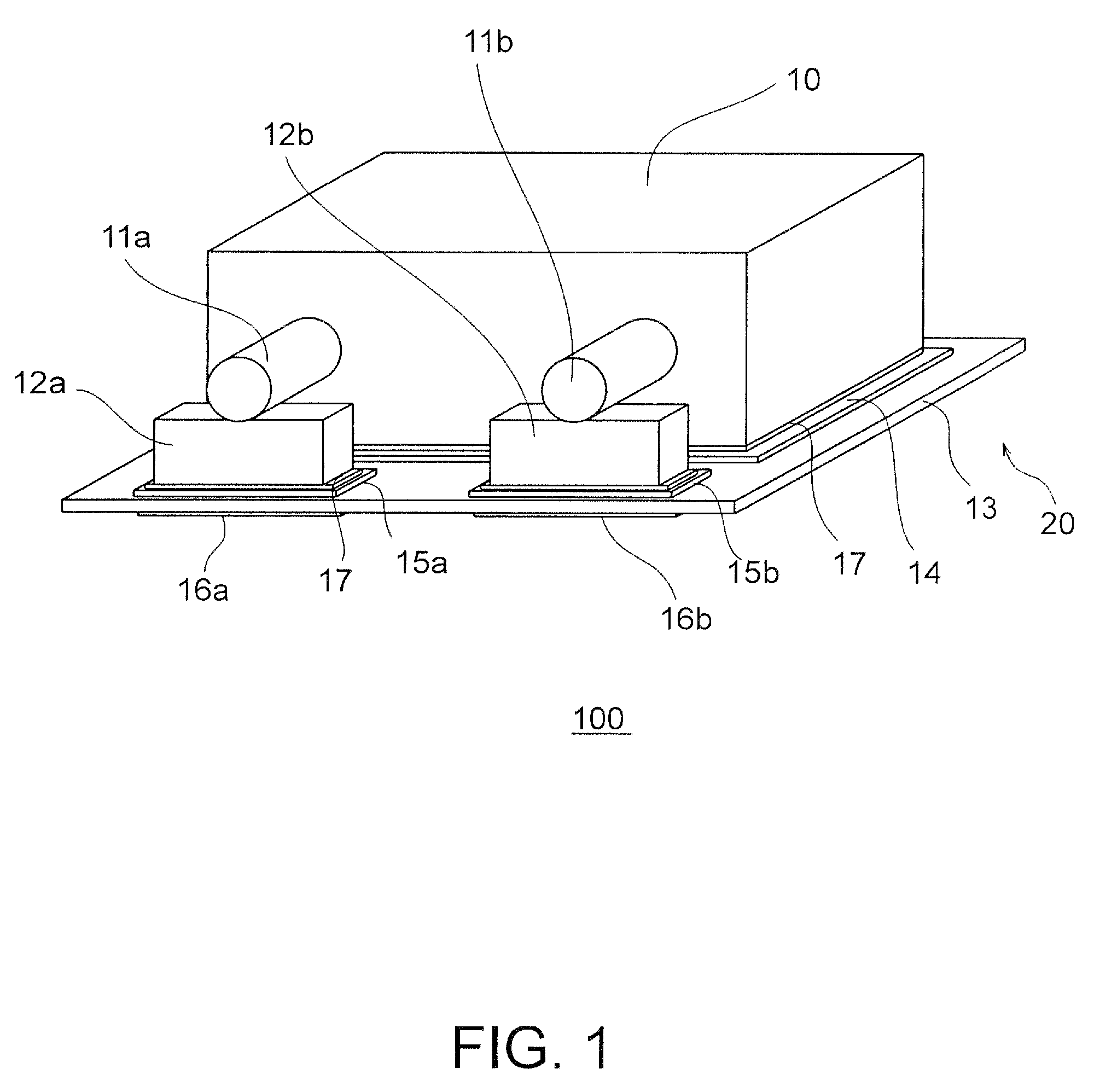
[0057]A procedure for preparing a capacitor element 10 containing tantalum, which is a valve metal, is described below. A tantalum powder is pressed around a tantalum wire with a press and then sintered at high temperature in a high vacuum, whereby a porous sintered body is obtained. An oxide coating made of Ta2O5 is formed on the porous sintered body. After the porous sintered body is dipped in a manganese nitrate solution, a MnO2 layer is formed on the porous sintered body by thermal decomposition. Graphite and silver layers are formed over the oxide coating, respectively, whereby the capacitor element 10 is obtained. If a conductive polymer such as polythiophene or polypyrrole is used instead of MnO2, which is a part of the cathode layer, a capacitor element having low ESR can be obtained. Examples of a usable valve metal other than tantalum include niobium, aluminum, and titanium.

[0058]Two ...

example 2

[0063]A first anode lead 11a and second anode lead 11b having a shape as shown in FIG. 4 were used. A valve metal pattern extends in a capacitor element and has a repeated shape. The first and second anode leads 11a and 11b are portions that extend from the valve metal pattern in substantially parallel to each other. Unlike the anode leads of Example 1, the first and second anode leads 11a and 11b were prepared in such a manner that a tantalum sheet with a thickness of 100 μm was punched with a die. The distance between the centers of the first and second anode leads 11a and 11b is 2.0 mm. The valve metal pattern has nine bent portions disposed in the capacitor element and has a shape symmetric with respect to the center line between the first and second anode leads 11a and 11b. Other portions are substantially the same as those described in Example 1.

example 3

[0064]In this example, a capacitor 100a has a structure as shown in FIG. 5A.

[0065]A first anode lead 11a and second anode lead 11b each having a shape as shown in FIG. 5B were used. The first and second anode leads 11a and 11b are different in shape from each other. The first and second anode leads 11a and 11b were designed such that the second anode lead 11b had an ESL less than that of the first anode lead 11a. There are two bent portions in a capacitor element used. The second anode lead 11b is wide and has an inner portion extending in the capacitor element at a constant width. The second anode lead 11b is wider than the first anode lead 11a; hence, ties have different sizes and anode lead tie-connecting portions have different sizes. In particular, a wide tie 12b is used for the second anode lead 11b having a greater width and a narrow tie 12a is used for the first anode lead 11a having a less width as shown in FIG. 5A. A wide anode lead tie-connecting portion 15b is used for t...


PUM

PropertyMeasurementUnit
thicknessaaaaaaaaaa
thicknessaaaaaaaaaa
thicknessaaaaaaaaaa

Abstract

A multiterminal solid electrolytic capacitor includes a capacitor element including a porous sintered body which includes a plurality of anode leads projecting from a surface of the porous sintered body and which is made from a valve metal powder, a dielectric oxide coating disposed on the porous sintered body, and a cathode including a solid electrolyte layer disposed on the dielectric oxide coating. The multiterminal solid electrolytic capacitor further includes a substrate which carries the capacitor element, which includes a plurality of anode-mounting terminals and a cathode-mounting terminal, and which is covered with resin. The anode leads are portions of a valve metal pattern which extends in the porous sintered body and which bends at a plurality of locations so as to have a desired path length.

Description

[0001]This application is based upon and claims the benefit of priority from Japanese patent application No. 2007-272553, filed on Oct. 19, 2007, the disclosure of which is incorporated herein in its entirety by reference.BACKGROUND OF THE INVENTION[0002]1. Field of the Invention[0003]The present invention relates to solid electrolytic capacitors and particularly relates to a multiterminal solid electrolytic capacitor.[0004]2. Description of the Related Art[0005]Solid electrolytic capacitors using as anode a valve, or valve action, metal such as tantalum or niobium are compact, have high capacitance and good frequency properties, and therefore are widely used in decoupling circuits or power supply circuits for central processing units (CPUs).[0006]The performance increase of recent electronic devices increases the operation speed of semiconductor devices and the like; hence, high-frequency noise tends to occur. High-frequency noise causes problems such as equipment errors and howls ...

Claims


Application Information

Patent Timeline
Patent Type & Authority Applications(United States)
IPC IPC(8): H01G9/00
CPCH01G9/012H01G4/228H01G9/15H01G9/052
Inventor MIZUKOSHI, TAKASHISAKATA, KOJIYOSHIDA, KATSUHIROYOSHINARI, TETSUYA
Owner TOKIN CORP
Why Eureka
Try Eureka