
Copper clad laminate

Inactive Publication Date: 2009-06-04
UBE IND LTD
View PDF10 Cites 23 Cited by
  • Summary
  • Abstract
  • Description
  • Claims
  • Application Information

AI Technical Summary

Benefits of technology

[0048]A copper-clad laminate of the present invention is prepared by laminating a copper foil with a thickness of 1 to 18 μm on one side or both sides of a polyimide film with a thickness of 5 to 20 μm by thermocompression bonding. A thickness of the polyimide film is preferably 5 to 15 μm. The copper foil is preferably a rolled copper foil with a thickness of 12 μm or less, particularly 10 to 12 μm. By making the polyimide film and the copper foil thinner as above, the very high flexibility may be achieved. For example, when a thickness of the polyimide film was reduced from 25 μm to 15 μm, an MIT folding endurance was approximately doubled or more in both MD and TD. When a thickness of the copper foil was reduced from 18 μm to 12 μm without changing a thickness of the polyimide film, an MIT folding endurance was increased in both MD and TD.
[0049]Particularly, when a copper foil used is a rolled copper foil having a tensile strength before heat treatment of 300 N / mm2 or more, and a ratio of tensile strength after heat treatment at 180° C. for 1 hour as defined by the above equation (1) of 33% or less, the flexibility may be improved more significantly by making the polyimide film and the copper foil thinner.
[0050]A copper-clad laminate of the present invention preferably has an MIT folding endurance of about 2000 times or more in both MD and TD, and the MIT folding endurance can be increased to about 3000 times or more, about 3700 times or more, about 4000 times or more, about 5000 times or more, and furthermore about 7000 times or more by selecting thicknesses of the polyimide film and the copper foil, and the type of the copper foil.
[0051]On the other hand, when the copper foil and the polyimide film are thinner, there may be formed wrinkles in a part contacting a roller during the lamination step for preparing a long copper-clad laminate, leading to a reduced yield due to defective appearance after lamination. Particularly, when using a thin polyimide film having a thickness of 25 μm or less, it is difficult to continuously manufacture a copper-clad laminate in the light of feeding properties.
[0052]A thermocompression-bonding multilayer polyimide film having a thermoplastic polyimide layer in which polyimide particles are dispersed on one side or both sides of a heat-resistant polyimide layer may be used as a polyimide film, to improve slipping property of the surface of the polyimide film and to eliminate defective appearance such as wrinkles in the copper-clad laminate obtained as checked over the whole length. Particularly, the thermoplastic polyimide layer preferably contains polyimide particles with a median size of 0.3 to 0.8 μm and the maximum size of 2 μm or less dispersed within at least a depth of 0.5 μm, more preferably 0.7 μm from its surface in a ratio of about 0.5 to 10% by weight relative to the polyimide in the polyimide surface layer, and does not contain an inorganic powder substantially. When using this polyimide film with a thickness of 25 μm or less, a copper-clad laminate without any defect in appearance may be obtained.

Problems solved by technology

However, a conventional copper-clad laminate comprising a polyimide film with a thickness of about 25 μm may not be adequately flexible.
Furthermore, a polyimide film may not have sufficiently adhesive properties.
Although being effective for improving adhesiveness, however, these methods require the use of an adhesive other than a polyimide, for example, an epoxy resin adhesive, leading to deterioration in heat resistance of the flexible substrate as a whole.
However, when this thermocompression-bonding multilayer polyimide film has a smooth surface, it has a larger friction against a roll, for example, during film formation in which the film is winded onto a wind-up roll or during lamination with a copper foil, causing troubles such as wrinkle formation and twisting around a roll, which may restrict winding.
However, the first method of surface treatment has a drawback that the appearance of the film is apt to be impaired due to excessive roughness formed of the film surface.
In the second method wherein an inorganic powder is mixed with a solution of a polyamic acid to prepare a polyimide film, it is difficult to disperse the inorganic powder in the polyamic acid solution homogeneously, without using a special dispersing device.
In the third method, similarly, it is difficult to disperse a fine-particulate inorganic powder homogeneously, and the use of an inorganic powder with a larger particle size may lead to the same problem as that encountered in the second method.
Therefore, when these methods in which inorganic fillers are added are applied to a copper-clad laminate for a COF requiring a fine pattern, a protrusion on a thermoplastic polyimide surface may hinder the formation of fine pitches.

Method used


Image

  • Copper clad laminate
  • Copper clad laminate

Examples


reference example 1

[0159]Preparation Example of a Particulate Polyimide

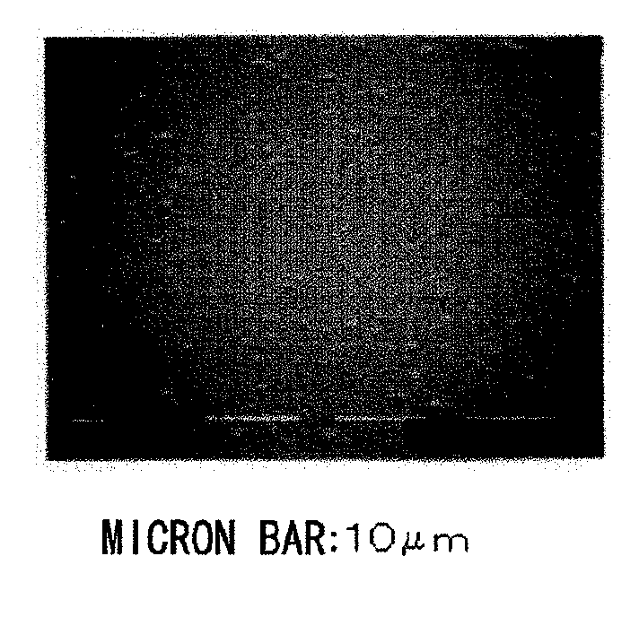
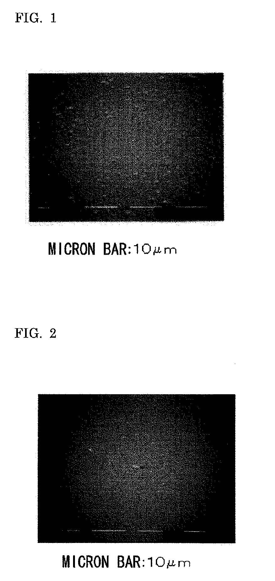
[0160]A particulate polyimide used was prepared by dissolving p-phenylenediamine and pyromellitic acid dianhydride in N,N′-dimethylacetamide, adding a dispersing agent (dispersant: 0.5% by weight relative to the monomers), and then gradually heating the resulting mixture to 160° C. in a nitrogen atmosphere with stirring (40 rpm), and after reaching the temperature, stirring the mixture for 3 hours. The particle-size distribution of the particulate polyimide obtained was determined by a laser diffraction / scattering particle-size distribution measurement device, and as a result, the median size was 0.3 μm and the distribution range was 0.1 to 1 μm. Furthermore, the shape of the particulate polyimide was determined by SEM observation, and as a result, they were cylindrical particles with a ratio of a major axis to a minor axis of 3 to 6.

reference example 2

[0161]Preparation Example of a Thermocompression-Bonding Multilayer Polyimide Film Having Improved Slipping Property

[0162]To N-methyl-2-pyrrolidone were added para-phenylenediamine (PPD) and 3,3′,4,4′-biphenyltetracarboxylic acid dianhydride (s-BPDA) in a molar ratio of 1000:998 such that a monomer concentration was 18% (by weight, the same shall apply hereinafter), and then the mixture was reacted at 50° C. for 3 hours, to give a polyamic acid solution having a solution viscosity of about 1500 poise at 25° C. (a dope for a heat-resistant polyimide). Separately, to N-methyl-2-pyrrolidone were added 1,3-bis(4-aminophenoxy) benzene (TPE-R) and 2,3,3′,4′-biphenyltetracarboxylic acid dianhydride (a-BPDA) in a molar ratio of 1000:1000 such that a monomer concentration was 22%, and further was added triphenyl phosphate in 0.1% by weight relative to the monomers, and then the mixture was reacted at 5° C. for one hour. To the resulting polyamic acid solution having a solution viscosity of a...

reference example 3

[0174]Preparation Example of a Thermocompression-Bonding Multilayer Polyimide Film

[0175]A long three-layer extruded polyimide film was winded onto a wind-up roll as described in Reference Example 2, except that no polyimide particles were added to a dope for a thermoplastic polyimide in a polyimide surface layer. The three-layer extruded polyimide film obtained had the following properties.

[0176]Thermocompression-bonding multilayer polyimide film:[0177]Thickness pattern: 3 μm / 9 μm / 3 μm (total 15 μm),[0178]Static friction coefficient: 1.00 or more.


PUM

PropertyMeasurementUnit
Temperatureaaaaaaaaaa
Lengthaaaaaaaaaa

Abstract

A copper-clad laminate is prepared by laminating a copper foil on one side or both sides of a polyimide film by thermocompression bonding. The flexibility of the copper-clad laminate is remarkably improved by employing a polyimide film having a thickness of 5 to 20 μm and a copper foil having a thickness of 1 to 18 μm.

Description

TECHNICAL FIELD[0001]The present invention relates to a highly flexible copper-clad laminate wherein a copper foil is laminated onto a polyimide film.BACKGROUND ART[0002]A polyimide film has been used for a laminated sheet, a flexible printed-circuit board and so forth, because of its excellent heat resistance, chemical resistance, mechanical strength, electric properties and so on.[0003]For example, a commonly used flexible printed circuit board (FPC) is a copper-clad laminate wherein a copper foil is laminated on one side or both sides of a polyimide film (Patent documents 1-3). A polyimide film used generally has a thickness of about 25 μm as the Examples in Patent documents 1-3.[0004]At present, a copper-clad laminate, typically a substrate for electronic parts, requires excellent mechanical properties and higher flexibility. In particular, when a copper-clad laminate is applied to a hinge, it is needed to be highly flexible. However, a conventional copper-clad laminate comprisi...

Claims


Application Information

Patent Timeline
IPC IPC(8): B32B15/08B29C48/08B29C48/18
CPCB29C47/0021B32B2457/08B29K2079/08B29K2105/256B32B15/08B32B15/20B32B37/04B32B2309/02B32B2309/105B32B2311/12B32B2379/08H05K1/0346H05K1/036H05K3/022H05K3/025H05K2201/0129H05K2201/0154H05K2201/0212H05K2201/0355H05K2203/068B32B27/281B32B2250/03B32B2250/40B32B2307/306B32B2307/54B32B2457/00B29C47/06B29C48/08B29C48/18Y10T428/31681B32B15/088B29C48/16B32B2264/0214
Inventor NARUI, KOHJIHASHIMOTO, MASAFUMIKOCHIYAMA, TAKURO
Owner UBE IND LTD
Learn More