Magnetic element with thermally-assisted writing

a technology of magnetic elements and thermally assisted writing, which is applied in the direction of recording/reproducing/erasing methods, instruments, and record information storage, etc., can solve the problems of limited capacity, limited integration, and easy to see the limits of this architecture, and achieve good trapping of the storage layer and high magnetoresistance efficiency

Active Publication Date: 2009-06-11
COMMISSARIAT A LENERGIE ATOMIQUE ET AUX ENERGIES ALTERNATIVES
View PDF9 Cites 17 Cited by
  • Summary
  • Abstract
  • Description
  • Claims
  • Application Information

AI Technical Summary

Benefits of technology

[0059]The object of the present invention is to propose precisely such random-access magnetic memories or logic elements with thermally-assisted writing using a field or spin transfer and, more especially, using, as a storage cell, a magnetic tunnel junction having a tunnel barrier made of MgO because of its magnetic characteristics and, in particular, in order to simultaneously obtain high magnetoresistance efficiency and good trapping of the storage layer.

Problems solved by technology

Because of its architecture, this technology makes it possible to produce non-volatile memories using technology that is simple but which has a limited capacity.
The fact that the storage cells are connected in series along each line limits possible integration because the signal becomes weaker and weaker as the number of cells increases.
Given the nature of the mechanism for writing these storage cells, the limits of this architecture are readily apparent.
Since the distribution function of the reversal fields for all the storage cells is wide (in fact it is not uniform because of fabrication constraints and inherent statistical fluctuations), the magnetic field at the selected storage cell must exceed the highest reversal field in the statistical distribution, at the risk of inadvertently reversing certain storage cells located on the corresponding row or column, where the reversal field in the lower part of the distribution is weaker than the magnetic field generated by the row or column alone.
In addition, the power consumption of a memory which uses such an external magnetic field will be higher, the wider the distribution of the reversal field.
Moreover, given the fact that, generally speaking, the average value of the reversal field increases as the size of storage cells decreases and cell size tends to decrease in order to save space, future product generations are likely to require even higher currents.
Another drawback of these prior-art memories is the stability of the magnetisation of the free layer with respect to thermal fluctuations as the size of the storage cell decreases.
But doing this increases the magnetic field which is required in order to obtain magnetic switching and hence also increases the power consumed in order to generate the field required to obtain magnetic switching.
Notwithstanding these advantages, one is nevertheless confronted with certain difficulties in terms of fabrication technology.
However, the situation is totally different if one uses magnetic tunnel junctions based on crystalline or textured magnesium oxide.
Because of this, one is confronted by the difficulty of achieving coexistence of the following in a trilayer stack: MgO lower ferromagnetic layer / tunnel barrier / upper magnetic layer having a high magnetoresistance ratio and body-centred cubic structure with an upper bilayer constituting the ferromagnetic / antiferromagnetic storage layers with a high exchange anisotropy field obtained with a face-centred cubic structure, even though both these entities have a different preferential crystallographic structure.
It goes without saying that, although the above discussion is based on cases involving magnetic tunnel junctions which presuppose the presence of a tunnel barrier which separates the reference layer from the storage layer, the same problems of adapting the crystallographic structures are encountered in cases where semiconductor separation layers (for instance germanium, silicon or GaAs) or metal / heterogeneous oxide separation layers such as so-called confined-current-paths layers, developed in the context of magnetoresistive read heads for hard disks, are used.

Method used


Image

  • Magnetic element with thermally-assisted writing
  • Magnetic element with thermally-assisted writing
  • Magnetic element with thermally-assisted writing

Examples


second embodiment

[0107]In the invention, it is also possible to insert heterogeneous metal oxides in the form of thin layers obtained, for example, by oxidising thin layers of a compound such as Al1-xCux, x being within the range 0.1 to 10%. This type of layer was developed for magnetoresistive heads which use confined current paths. Because aluminium's affinity for oxygen is much greater than copper's, after oxidation the layers consist of AlOx layers pierced by copper metallised holes having a relatively well-controlled density and size. The density and the size of these holes are determined by the quantity of copper mixed with the aluminium during the AlCu alloy deposition phase prior to oxidation and by the oxidation conditions (pressure, temperature during oxidation).

[0108]More generally speaking, one can use any form of heterogeneous alloy having the general formula: My(NOx)1-y where M is a transition metal selected from the group comprising nickel, cobalt and iron or a noble metal or an alloy...

first embodiment

[0113]As in the first embodiment, it is also possible to insert several layers (typically as many as 2 or 3) of such heterogeneous alloys in the stack whilst nevertheless maintaining the required thickness in order to preserve good magnetic coherence of the entire storage layer and appropriate exchange field properties. In other words, the various layers which make up the storage layer must be sufficiently magnetically coupled to respond as a single magnetic layer, the coercivity of which is less than the exchange anisotropy field, the latter typically equaling several dozen to several hundred oersteds in normal mode, i.e. other than at the time of a write.

third embodiment

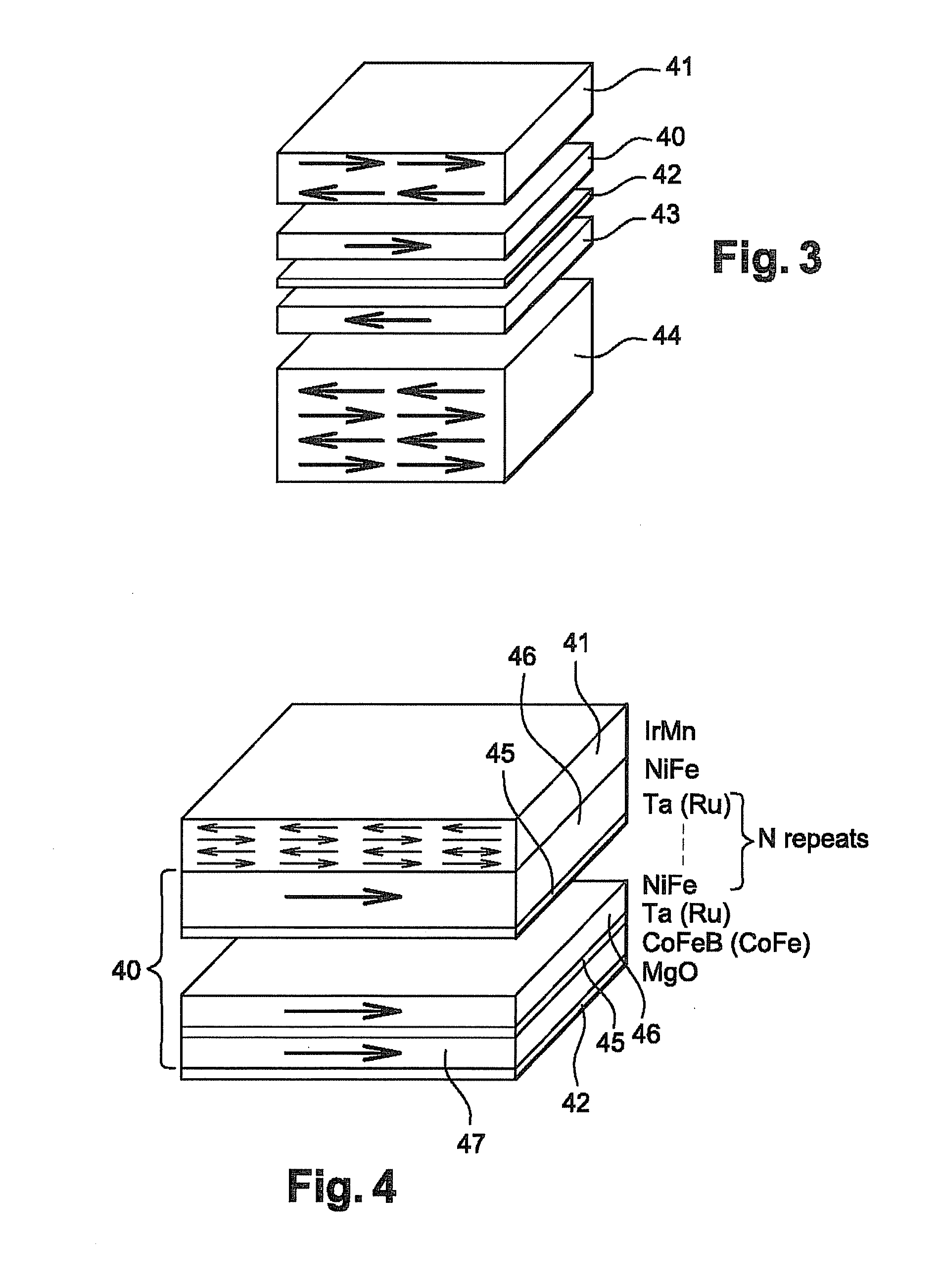
[0114]In the invention, the layer of amorphous or quasi-amorphous material inserted into the storage layer can be obtained by a natural or plasma oxidation stage which takes place during growth of the upper magnetic layer of the tunnel junction. For example, one can deposit, on the MgO tunnel barrier, a first 2 nm thick layer of CoFeB or CoFe with a body-centred cubic crystal lattice (iron concentration in excess of 30% and preferably around 50%). The structure obtained is then exposed to the atmosphere or oxygen so as to naturally oxidise the surface of the CoFeB or CoFe in order to obtain formation of a layer of CoFeBOx or CoFeOx.

[0115]After this operation, the upper layer can be grown using a face-centred cubic type magnetic material such as CoFe having an iron concentration less than 30%, for example, Co90Fex or NiFe.

[0116]This technique for implementing a nanometric oxide layer from the oxidation surface of a previously deposited magnetic layer is identical to that already deve...


PUM

PropertyMeasurementUnit
thicknessaaaaaaaaaa
thicknessaaaaaaaaaa
magnetic thicknessaaaaaaaaaa

Abstract

This magnetic element with thermally-assisted writing using a field or spin transfer comprises a magnetic reference layer referred to as the “trapped layer”, the magnetisation of which is in a fixed direction; a magnetic storage layer called the “free layer” having a variable magnetisation direction and consisting of a layer made of a ferromagnetic material with magnetisation in the plane of the layer and magnetically coupled to a magnetisation-trapping layer made of an antiferromagnetic material; a semiconductor or an insulating layer with confined-current-paths sandwiched between the reference layer and the storage layer. At least one bilayer consisting respectively of an amorphous or quasi-amorphous material and a material having the same structure or the same crystal lattice as the antiferromagnetic layer is placed in the storage layer between ferromagnetic layer which is in contact with the semiconductor or insulating layer with confined-current-paths and antiferromagnetic layer.

Description

FIELD OF THE INVENTION[0001]The present invention relates to the field of magnetic tunnel junction or magnetic spin-valve elements such as those used in non-volatile magnetic random-access memories which can be used, in a known manner, to store, read and write data in electronic systems. More specifically, it applies to magnetic random-access memories, commonly referred to by the abbreviation “MRAM”, which consist of a number of storage cells each formed by a Magnetic Tunnel Junction, which is usually referred to by the abbreviation “MTJ”. Relatedly, the present invention also relates to logic elements with magnetic layers if they use at least one magnetic tunnel junction or spin valve.[0002]In the text which follows, the term “magnetic element” is taken to mean a stack of magnetic layers comprising at least one trapped layer, a free layer and, between them, an insulating or semiconductor layer or insulating layer with confined-current-paths. The terms “trapped layer” and “free laye...

Claims


Application Information

Patent Timeline
Patent Type & Authority Applications(United States)
IPC IPC(8): G11B5/02
CPCG11C11/16H01L43/10H01L27/228G11C11/1675H10B61/22H10N50/85H10N50/01
Inventor PREJBEANU, LUCIANMAUNOURY, CECILEDIENY, BERNARDDUCRUET, CLARISSESOUSA, RICARDO
Owner COMMISSARIAT A LENERGIE ATOMIQUE ET AUX ENERGIES ALTERNATIVES
Why Eureka
Try Eureka