Methods for laser cutting and processing tubing to make medical devices

Inactive Publication Date: 2009-06-18
ABBOTT CARDIOVASCULAR
View PDF20 Cites 19 Cited by
  • Summary
  • Abstract
  • Description
  • Claims
  • Application Information

AI Technical Summary

Benefits of technology

[0035]In yet another aspect of the present invention, cleaning and polishing of the cut workpiece can be accomplished without application of excessive forces which could otherwise damage the often intricately cut workpiece. In this aspect, the cut tubular workpiece could be subjected to compressed air which will cause any slag affixed to the surface to be quickly removed. In one particular aspect, a mounting fixture having a number of outlet openings could be utilized to supply compressed air in the form of individual jets to the surface of the tubular workpiece. A compressed ai

Problems solved by technology

This undesirable burning or partial vaporization of the opposite sidewall is called “burn through” and can result in the weakening of opposite sidewall.
In some cases, burn through may result in the workpiece being discarded.
Oxidation can make a stent more susceptible to failure (e.g., cracking or fracture) during manufacturing or, if not completely removed, in use.
Additionally, recast material can be particularly difficult to remove without damaging the thin struts created by the laser cutting operation.
Therefore, both burn through and formation of recast material presents a formidable problem to the stent manufacturer.
Side walls of the slot or kerf also become oxidized during the cutting process, making the as-cut stent less ductile and thereby more susceptible to cracking or complete fracture during radial expansion or during other subsequent manufacturing steps.
Some methods require the physical removal of the recast material using a reamer or similar equipment and can often damage the thin struts of the stent.
While electropo

Method used


Image

  • Methods for laser cutting and processing tubing to make medical devices
  • Methods for laser cutting and processing tubing to make medical devices
  • Methods for laser cutting and processing tubing to make medical devices

Examples


Embodiment Construction

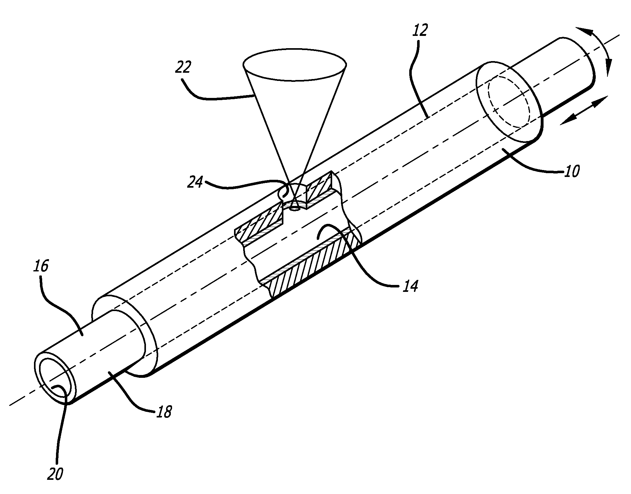
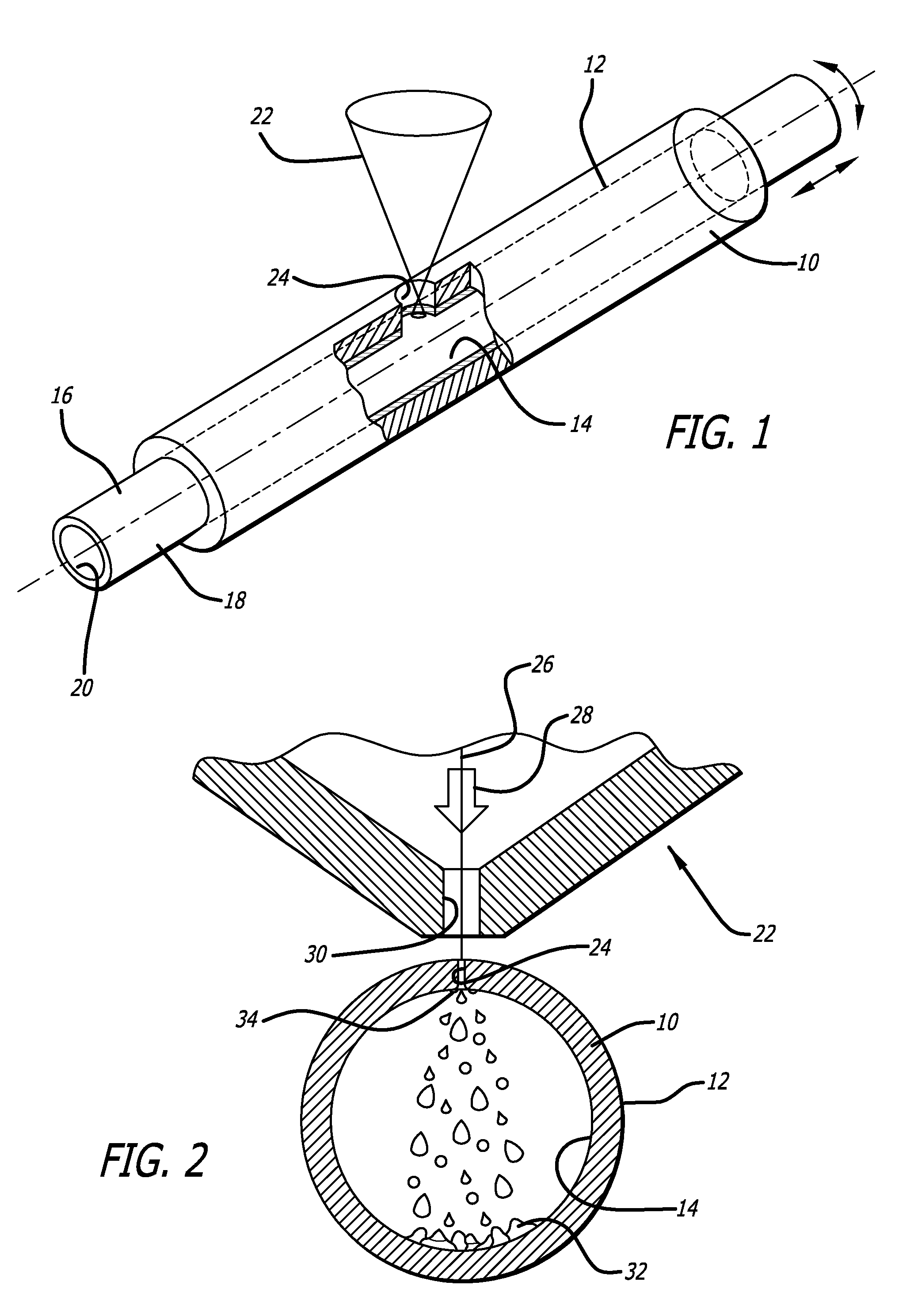
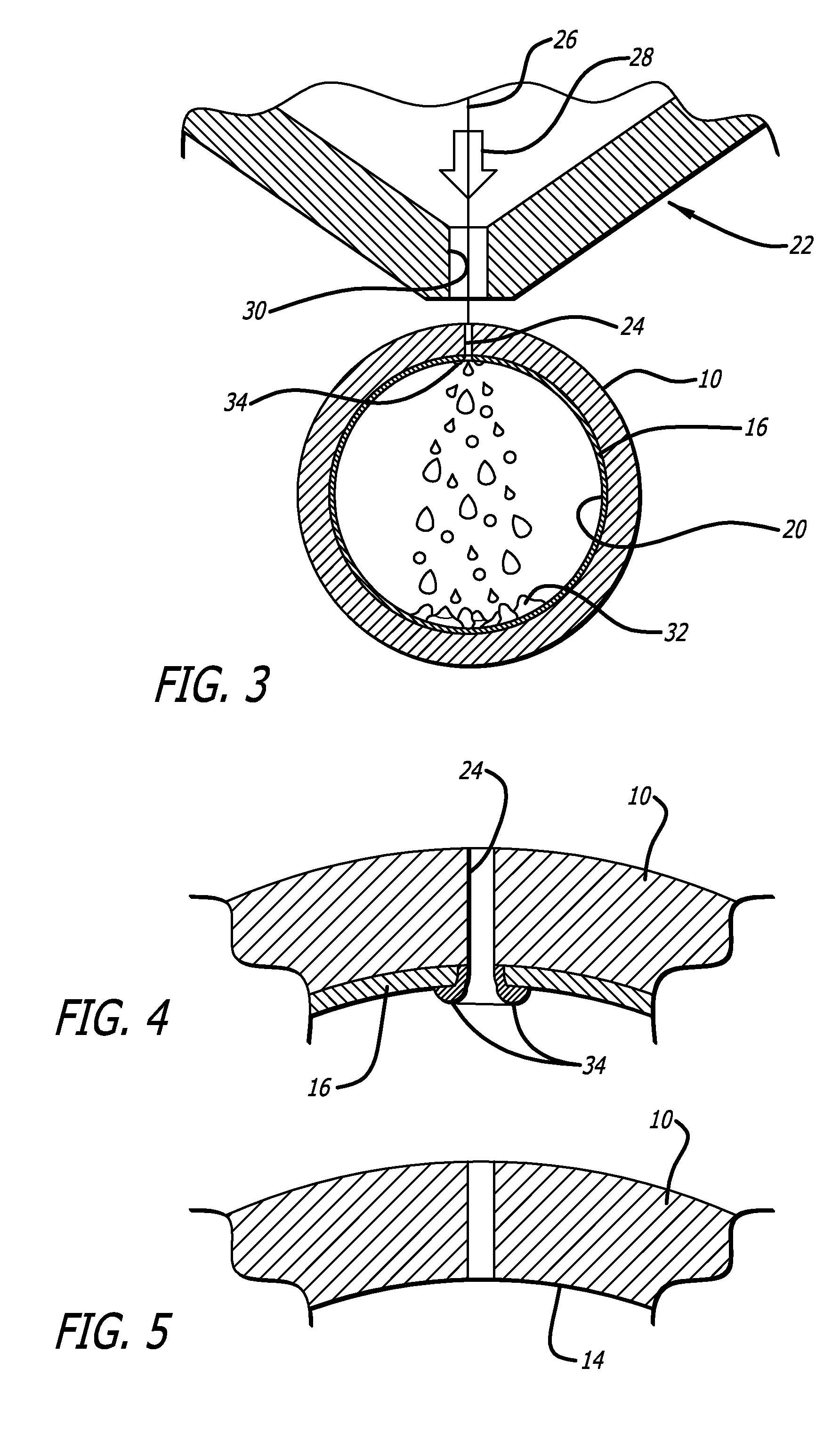
[0052]Referring now to the drawing in which reference numerals represent like or corresponding elements across the drawings, and particularly FIGS. 1 and 3-5, a method of making a device from a hollow tubular member 10 is generally disclosed. The present invention relates generally to methods for laser cutting a length of hollow tubing, or as is it referred to herein a “tubular member,” to form a device, typically a medical device, such as a stent. While most workpieces formed in accordance with the present invention are in the form of a tubular member having a circular cross section, the tubular member could have a non-circular cross section as well. For example, the tubular member could have a rectangular, oval, square, and the like cross section, if desired. Moreover, the invention is not limited to forming stents and has a wide application with respect to other laser cut medical devices and non-medical products, particularly products which require a high precision pattern that i...


PUM

PropertyMeasurementUnit
Timeaaaaaaaaaa
Energyaaaaaaaaaa

Abstract

A method for making a device includes providing a tubular member which will be formed into the device, masking at least a portion of the inner surface of the tubular member with a removable sacrificial material, selectively removing a portion of the tubular member and sacrificial material using a laser device, and mechanically removing the sacrificial material from the inner surface of the tubular member. Ultrasonic energy could be applied to a workpiece which is being laser cut to prevent any generated slag from welding itself to an exposed surface of the workpiece. A compressed fluid or gas, such as air, could be used to clean the surface of the laser-cut workpiece to remove slag formation which adheres to the surface of the cut workpiece.

Description

CROSS-REFERENCE TO RELATED APPLICATIONS[0001]This is a continuation-in-part application of U.S. Ser. No. 11 / 756,305, filed May 31, 2007, the contents of which are hereby incorporated by reference.BACKGROUND OF THE INVENTION[0002]The present invention relates generally to methods for laser cutting and processing a hollow workpiece, such as a length of tubing. The present invention is more particularly directed to methods for fabricating medical devices, such as, for example, expandable endoprostheses, commonly known as stents, using processes which help to prevent damage to the workpiece when cutting the workpiece with a laser apparatus and when later processing the cut workpiece.[0003]Stents are particularly useful in the treatment and repair of blood vessels after a stenosis has been compressed by percutaneous transluminal coronary angioplasty (PTCA), percutaneous transluminal angioplasty (PTA), or removed by atherectomy or other means, to help improve the outcome of the procedure ...

Claims


Application Information

Patent Timeline
IPC IPC(8): B23P13/04
CPCA61F2/91B23K26/16Y10T29/49995B23K2201/06B21D7/16B23K26/38B23K2101/06B23K26/00B23P13/00B23K26/0093B23K28/02
Inventor BIALAS, MICHAEL R.BARBIER, ROBERT P.STRAUSS, DAVIDMACKIEWICZ, DAVIDKIENZLE, PIUSBALDI, MIHAELA
Owner ABBOTT CARDIOVASCULAR
Why Eureka
Try Eureka