Motor drive device, method, and cooling device using the same

a technology of motor drive and cooling device, which is applied in the direction of electronic commutators, pulse techniques, dynamo-electric converter control, etc., can solve the problems of large noise, large voltage applied to transistors, and rapid change of time waveform of regenerative current flowing through freewheel diodes, so as to reduce noise generated by fan motors and reduce circuit area , the effect of reducing the noise of electronic devices

Active Publication Date: 2009-06-18
ROHM CO LTD
View PDF3 Cites 27 Cited by
  • Summary
  • Abstract
  • Description
  • Claims
  • Application Information

AI Technical Summary

Benefits of technology

[0020]The abovementioned motor drive apparatus may be monolithically integrated on one semiconductor substrate. Furthermore, “monolithically integrated” includes cases in which all circuit component elements are formed on the semiconductor substrate, and cases in which main circuit component elements are integrated as a unit and some resistors, capacitors, or the like, for adjusting a circuit constant, may be arranged outside the semiconductor substrate. By integrating the motor drive apparatus on one LSI, it is possible to reduce circuit ar

Problems solved by technology

However, with the technology described in Patent Document 1, there have been cases in which time waveform of the regenerative current flowing via the freewheel diode changes rapidly, or has a large peak.
As a

Method used


Image

  • Motor drive device, method, and cooling device using the same
  • Motor drive device, method, and cooling device using the same
  • Motor drive device, method, and cooling device using the same

Examples


first embodiment

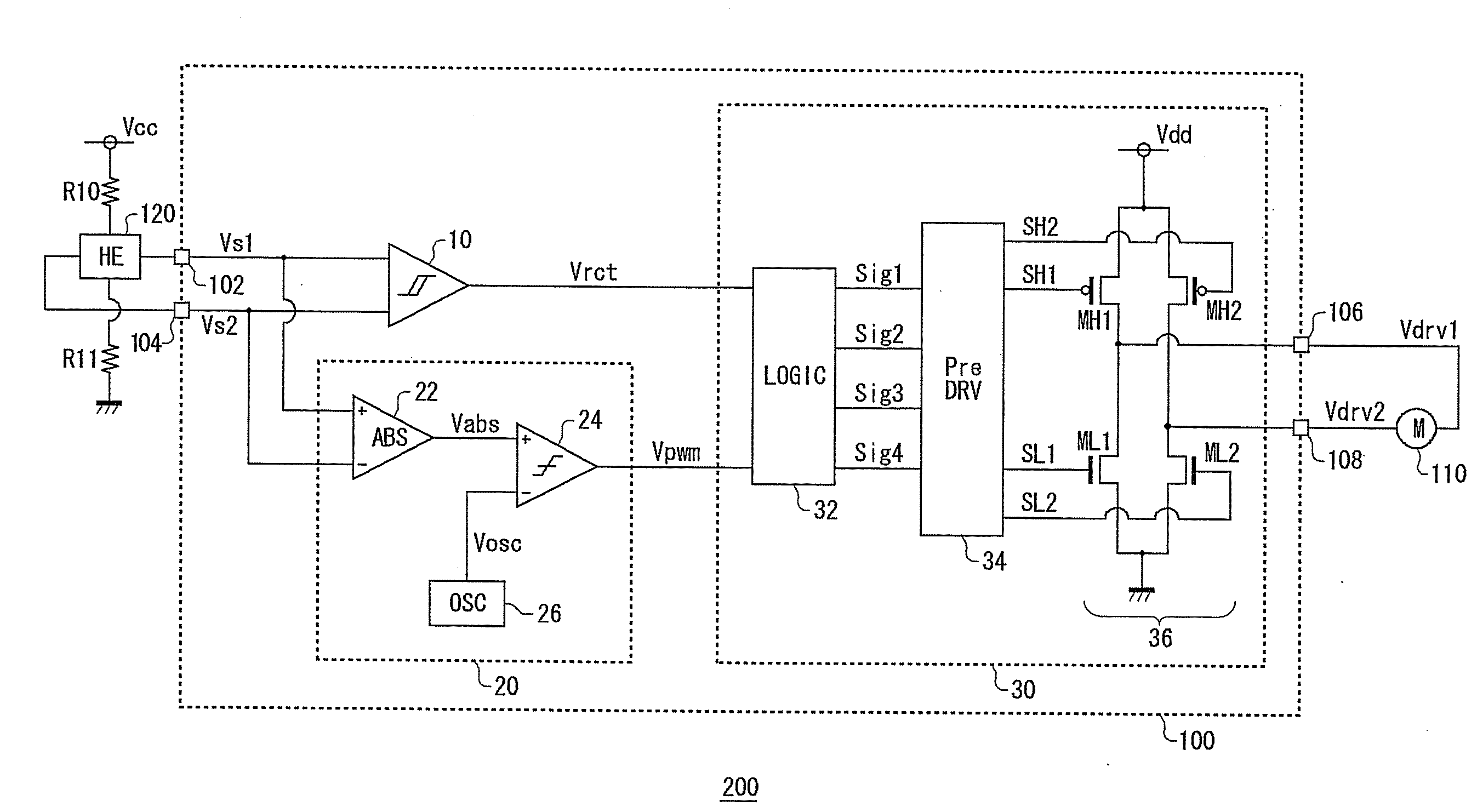
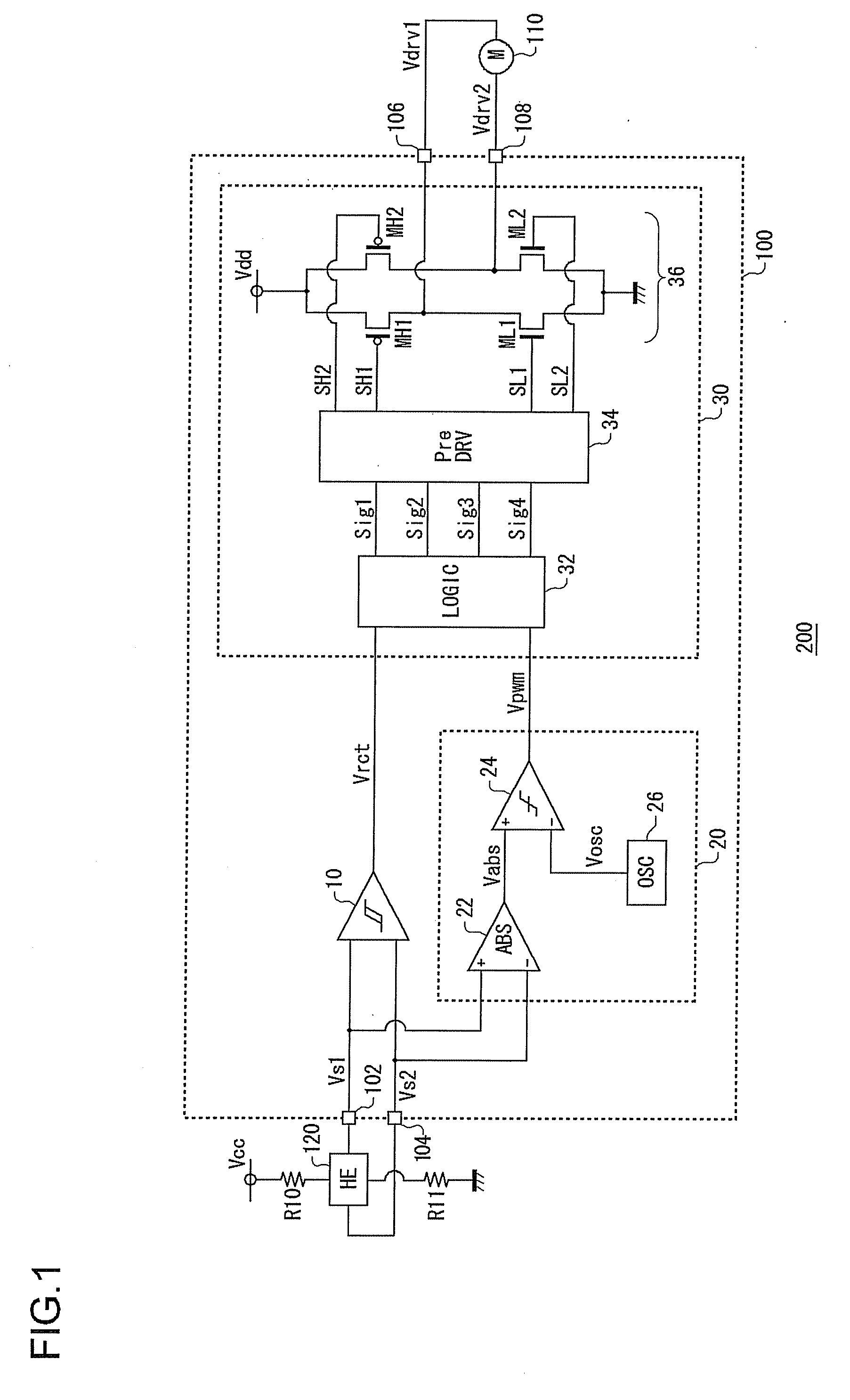
[0033]In an embodiment of the invention, an explanation is given concerning a motor drive apparatus used in a cooling system for cooling an electronic device such as a refrigerator, a personal computer, or the like. FIG. 1 is a circuit diagram showing a configuration of the cooling system 200 according to a first embodiment of the invention. The cooling system 200 includes a motor drive apparatus 100, a fan motor 110, and a Hall element 120.

[0034]The fan motor 110 is a single-phase full-wave motor, and is disposed opposite an object that is to be cooled, which is not shown in the figure. In the fan motor 110, a coil current, that is, an energization state, is controlled by a drive voltage outputted from the motor drive apparatus 100, and rotation is controlled.

[0035]The Hall element 120 is connected to a power supply line, to which a power supply voltage Vcc is applied via a resistor R10, and is grounded via a resistor R11. The size of a signal outputted from the Hall element 120 is...

second embodiment

[0058]In the first embodiment, an explanation was given concerning cases in which a single phase motor is driven linearly, for the energization time-period; in a second embodiment as below, however, an explanation is given concerning cases in which a single phase motor is driven by switching. FIG. 3 is a circuit diagram showing a configuration of a cooling system 200 according to the second embodiment. In FIG. 3, component elements that are identical or equivalent to component elements in the configuration of FIG. 1 are given the same reference symbols, and repeated explanations are omitted as appropriate.

[0059]A temperature detection circuit 130, which generates a temperature detection voltage Vth that is dependent on surrounding temperature of an object to be cooled, is connected to an external portion of the motor drive apparatus 100. The temperature detection circuit 130 includes a thermistor Rth and a resistor R12 connected in series between a reference voltage and ground. Volt...

third embodiment

[0063]In a third embodiment, an explanation is given concerning a cooling system 200 that controls a fan motor 110 based not on temperature, but on a pulse width modulated control signal Vcnt which controls the rotational frequency of a fan motor 110 that is to be driven. In the present embodiment, a motor drive apparatus 100 has a configuration similar to FIG. 3, and is provided with a smoothing circuit 140, instead of the temperature detection circuit 130. FIG. 4 is a circuit diagram showing a configuration of the smoothing circuit 140 of the cooling system 200 according to the third embodiment.

[0064]The smoothing circuit 140 smoothes the pulse width modulated control signal Vcnt which controls the rotational frequency of the fan motor 110, and outputs a result thereof as a direct current rotation control voltage Vcnt′.

[0065]The smoothing circuit 140 includes a transistor Q1, a capacitor C1, and a resistor R14. The control signal Vcnt is inputted to a base of the transistor Q1, an...


PUM


Abstract

In the motor drive apparatus, a Hall element outputs a first sinusoidal signal and a second sinusoidal signal, of mutually opposite phases, in accordance with rotor position. A hysteresis comparator compares the first sinusoidal signal and the second sinusoidal signal outputted from the Hall element, and outputs a rectangular wave signal. A pulse width modulation signal generation circuit detects timing at which phase switches, based on the first sinusoidal signal and the second sinusoidal signal outputted from the Hall element, and outputs a pulse width modulation signal in which duty ratio gradually changes, in a predetermined time-period in which the phase switches. A drive circuit combines the rectangular wave signal and the pulse width modulation signal by a logical operation, and drives the fan motor.

Description

BACKGROUND OF THE INVENTION[0001]1. Field of the Invention[0002]The present invention relates to a motor drive apparatus using a Hall element.[0003]2. Description of the Related Art[0004]As a method of driving a single-phase motor, a method is known in which rotor position is detected using a Hall element, and coil current is controlled by applying voltage to a coil of the single-phase motor in accordance with rotor position information, to control rotation of the rotor (Patent Document 1).[0005]Conventionally, as described in FIG. 1 of Patent Document 1, an output signal of the Hall element is inputted to a hysteresis comparator and converted to a rectangular wave signal, and the coil of the motor is energized to perform rotation control, by turning ON and OFF transistors forming a H-bridge circuit based on the rectangular wave signal. At this time, at timing in which phase is shifted, by delaying the rectangular wave signal outputted from the hysteresis comparator, a time-period (...

Claims


Application Information

Patent Timeline
IPC IPC(8): H02P6/16F04D25/08H02P6/06H02P6/08H02P6/26
CPCH02P6/008H03K17/6872H03K17/163H02P6/16H02P6/26
Inventor MISHIMA, TOMOFUMIMIYAJIMA, SATOSHI
Owner ROHM CO LTD
Why Eureka
Try Eureka