Method of making phosphor containing glass plate, method of making light emitting device

Active Publication Date: 2009-07-23
TOYODA GOSEI CO LTD +1
View PDF3 Cites 39 Cited by
  • Summary
  • Abstract
  • Description
  • Claims
  • Application Information

AI Technical Summary

Benefits of technology

[0019]It is an object of the invention to provide a method for making a light emitting device that is excellent in heat resi

Problems solved by technology

However, since the conventional white LED lamps use the transparent resin as the sealing material, the transparent resin near the LED chip may be yellowed due to light or heat etc. from the LED chip, so that the light extraction efficiency will deteriorate with time.
In particular, the yellowing of the transparent resin is notably caused when a short-wavelength LED chip for emitting blue light etc. with high energy.
Further, since the transparent resin has permeability to gases, the phosphor powder contained in the transparent resin may be reacted with gas (especially moisture) in the air, so that the phosphor characteristics can often deteriorate with time.
Because of this, it is difficult to keep the characteristics of these phosphors although they can be used as high excitation efficiency green or red phosphor.
As described, sealing by the transparent resin is insufficient to meet the heat resistance, the light resistance and the i

Method used


Image

  • Method of making phosphor containing glass plate, method of making light emitting device
  • Method of making phosphor containing glass plate, method of making light emitting device
  • Method of making phosphor containing glass plate, method of making light emitting device

Examples


Example

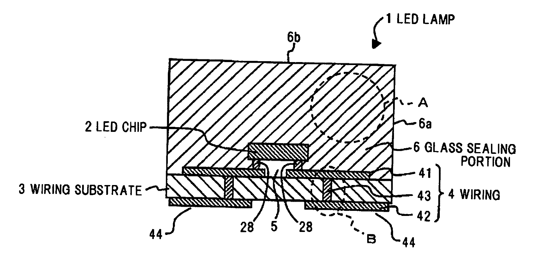
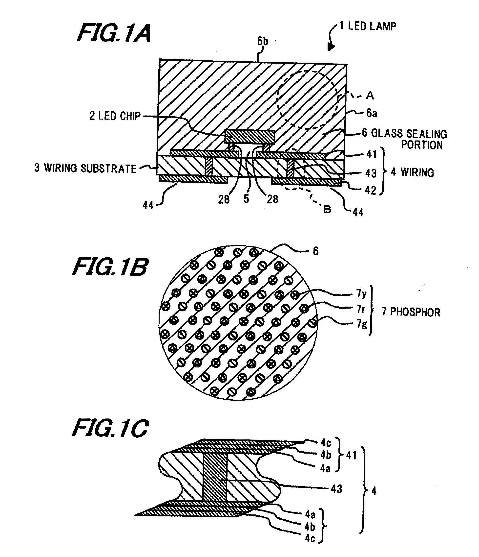
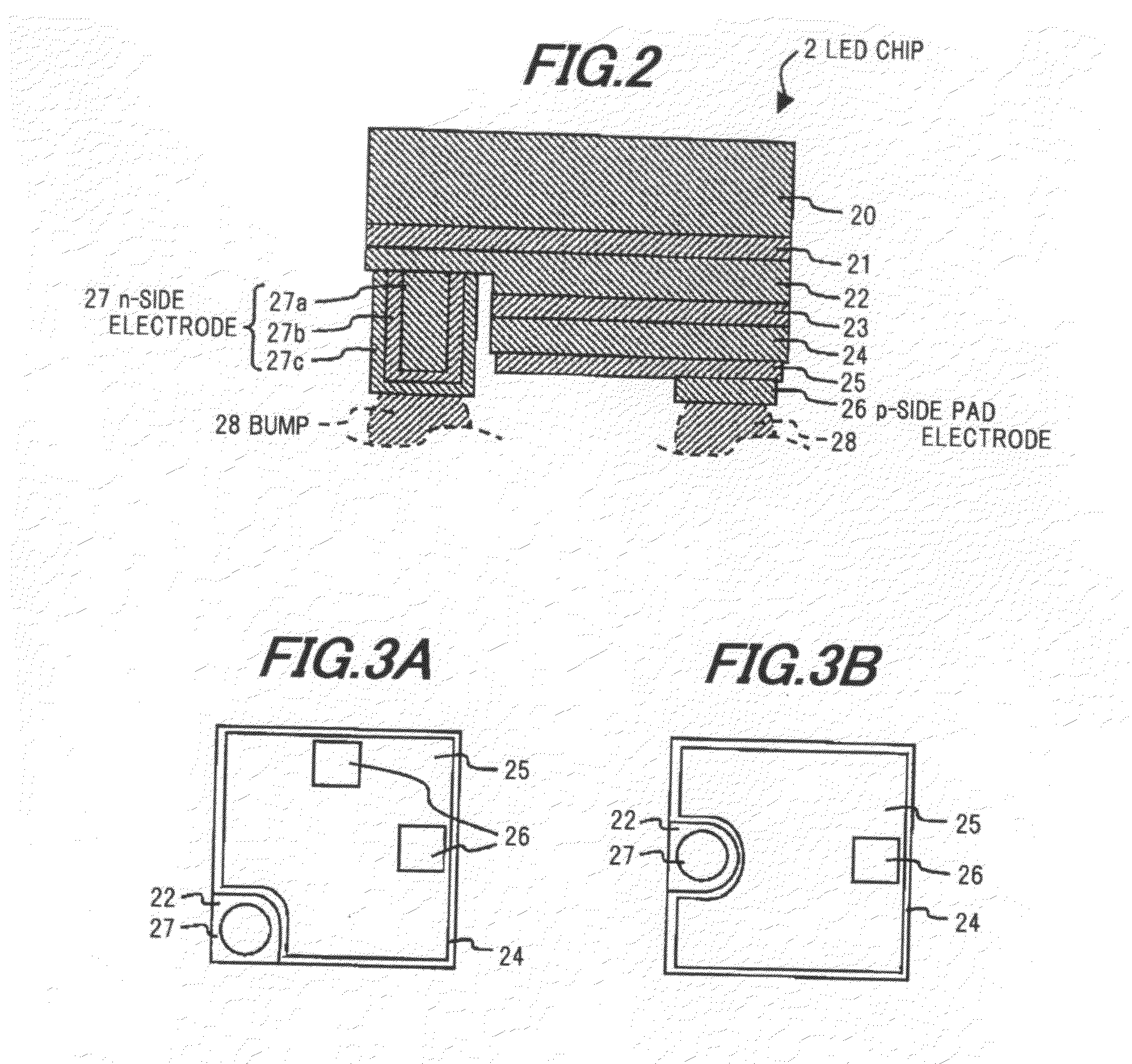
[0049]FIG. 1A to 7 show the preferred embodiment of the invention. FIGS. 1A to 1C are cross sectional views showing an LED lamp in the embodiment. FIG. 2 is a cross sectional view showing an LED chip used in the embodiment.

[0050]As shown in FIG. 1A, the LED lamp (=light emitting device) 1 is composed of a flip-chip type LED chip (=light emitting element) 2, a wiring substrate 3 for mounting the LED chip 2 thereon, a wiring 4 formed on or in the wiring substrate 3, and a glass sealing portion 6 sealing the LED chip 2, adhered to the wiring substrate 3 and containing a phosphor 7 therein.

[0051]As shown in FIG. 2, the LED chip 2 is composed of, grown sequentially on the surface of a crystal growth substrate 20, a buffer layer 21, an n-type layer 22, a light emitting layer 23 and a p-type layer 24 which are of gallium nitride-based semiconductor (Al1-X-YInXGaYN, 0≦X≦1, 0≦Y≦1, 0≦X+Y≦1), and formed by MOVPE (metalorganic vapor phase epitaxy). The LED chip 2 is epitaxially grown at 700° C....


PUM

PropertyMeasurementUnit
Pressureaaaaaaaaaa

Abstract

A method of making a light emitting device includes mixing a glass powder with a phosphor powder including at least one of a sulfide phosphor, an aluminate phosphor and a silicate phosphor to produce a mixed powder in which the phosphor powder is dispersed in the glass powder, heating and softening the mixed powder to provide an integrated material, and subsequently solidifying the integrated material to provide a phosphor-dispersed glass, and fusion-bonding the phosphor-dispersed glass onto a mounting portion on which a light emitting element is mounted by hot pressing, and simultaneously sealing the light emitting element with the phosphor-dispersed glass on the mounting portion.

Description

[0001]The present application is based on Japanese patent application Nos. 2007-336663 and 2008-253608 filed Dec. 27, 2007 and Sep. 30, 2008, respectively, the entire contents of which are incorporated herein by reference.BACKGROUND OF THE INVENTION[0002]1. Field of the Invention[0003]This invention relates to a method of making a phosphor containing glass plate and to a method of making a light emitting device by using the phosphor containing glass plate.[0004]2. Description of the Related Art[0005]In recent years, white LED (light emitting diode) lamps for emitting white light are practically used as a lighting system, a backlight for LCD (liquid crystal display) etc.[0006]In general, the white LED lamps are composed of a blue LED chip which is made of a group III nitride-based compound semiconductor for emitting blue light, and a transparent resin which is made of epoxy system, silicone system etc. for sealing the LED chip and contains a yellow phosphor powder that emits yellow w...

Claims


Application Information

Patent Timeline
IPC IPC(8): H01L21/00C03B19/00
CPCC03B19/063C03C8/24C03C14/004C03C14/006C03C27/00C09K11/7734C09K11/7741H01L2924/12041H01L33/501H01L2933/0041H01L24/97H01L2224/13H01L2924/00H01L2924/15787H01L2924/181Y02P40/57H01L2224/0508H01L2224/05573H01L2224/05568H01L2224/05023H01L2224/05124H01L2224/05644H01L2224/06102H01L2224/1703H01L2924/00014
Inventor YAMAGUCHI, SEIJINONOGAWA, TAKASHISUEHIRO, YOSHINOBUWATANABE, HIROKIAIDA, KAZUYA
Owner TOYODA GOSEI CO LTD
Why Eureka
Try Eureka