Process to prepare the self-stand electrode using porous supporter of electrode catalyst for fuel cell, a membrane electrode assembly comprising the same

a fuel cell and self-standing technology, applied in the field of porous electrodes, can solve the problems of deterioration of fuel cell performance, complicated manufacturing methods, and deterioration of durability, and achieve excellent performance, improve fuel cell performance, and enhance conductivity and electrochemical activity

Inactive Publication Date: 2009-08-13
HANWHA CHEMICAL CORPORATION
View PDF4 Cites 15 Cited by
  • Summary
  • Abstract
  • Description
  • Claims
  • Application Information

AI Technical Summary

Benefits of technology

[0007]It is an object of the present invention to provide a porous electrode for fuel cell, which introduces a macropore using a non-conductive porous substrate, and endows conductivity and electrochemical activity by coating catalyst ink having electrochemically excellent performance on the porous substrate to reduce a flooding phenomenon in a high current density operation region and to optimize a 3-phase interface, thereby making it possible to improve the performance of a fuel cell.

Problems solved by technology

In particular, a flooding phenomenon, which prevents inflow of the fuel gas as the water generating the electrode reaction in a high current density region is not discharged to remain in the electrode pore, interrupts the 3-phase interface from being formed in the electrode to cause deterioration of the performance of the fuel cell.
However, when using the metal mesh, a problem arises in that durability is deteriorated due to corrosion of the metal, and when using the electrode including adsorption porous material in the penetration hole inside the electrode substrate, a disadvantage arises in that a manufacturing method thereof is complicated.

Method used


Image

  • Process to prepare the self-stand electrode using porous supporter of electrode catalyst for fuel cell, a membrane electrode assembly comprising the same
  • Process to prepare the self-stand electrode using porous supporter of electrode catalyst for fuel cell, a membrane electrode assembly comprising the same
  • Process to prepare the self-stand electrode using porous supporter of electrode catalyst for fuel cell, a membrane electrode assembly comprising the same

Examples


example 1

(1) Preparation of Catalyst Ink

[0038]40 wt % Pt / C (Tanaka Kikinzoku Kogyo Kabushiki Kaisha) / water / isopropyl alcohol / ionomer (20% Nafion solution) are mixed at a mixing ratio 1:6:6:6 wt % / wt % shown in the publicly known document (J. H. Kim et al, J. Power Sources 135 (2004) 29.) and then put into a bath maintained at 4° C., thereby being stirred at 10,000 RPM using a homogenizer for two hours. The prepared catalyst ink is ripen for twenty-four hours and is sonificated for ten minutes before it is to be coated, thereby being used. The viscosity of the prepared catalyst ink is 200 cps and the d50 value of a secondary diameter of the catalyst particle is 0.65 μm.

(2) Coating of Catalyst Ink

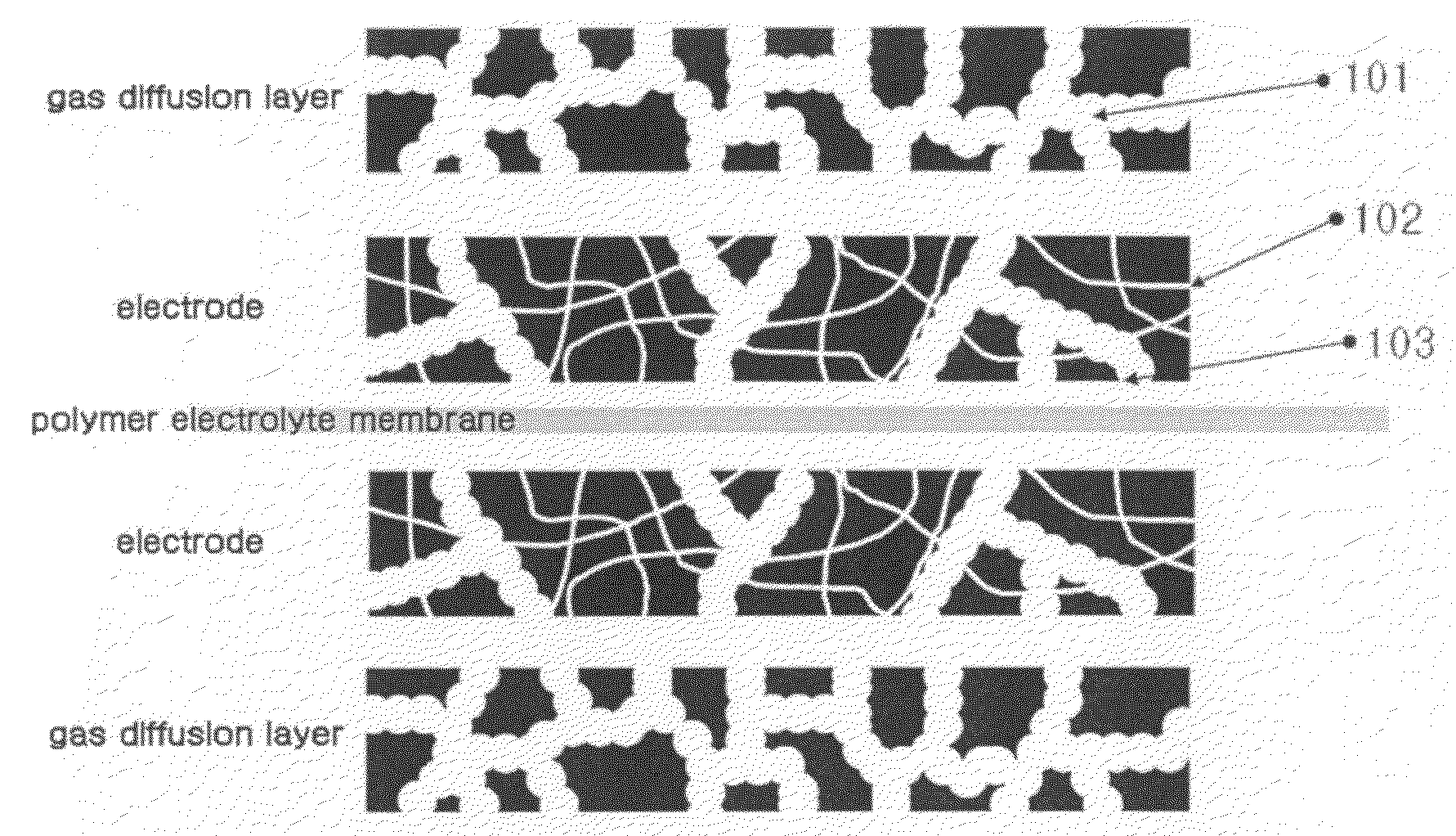
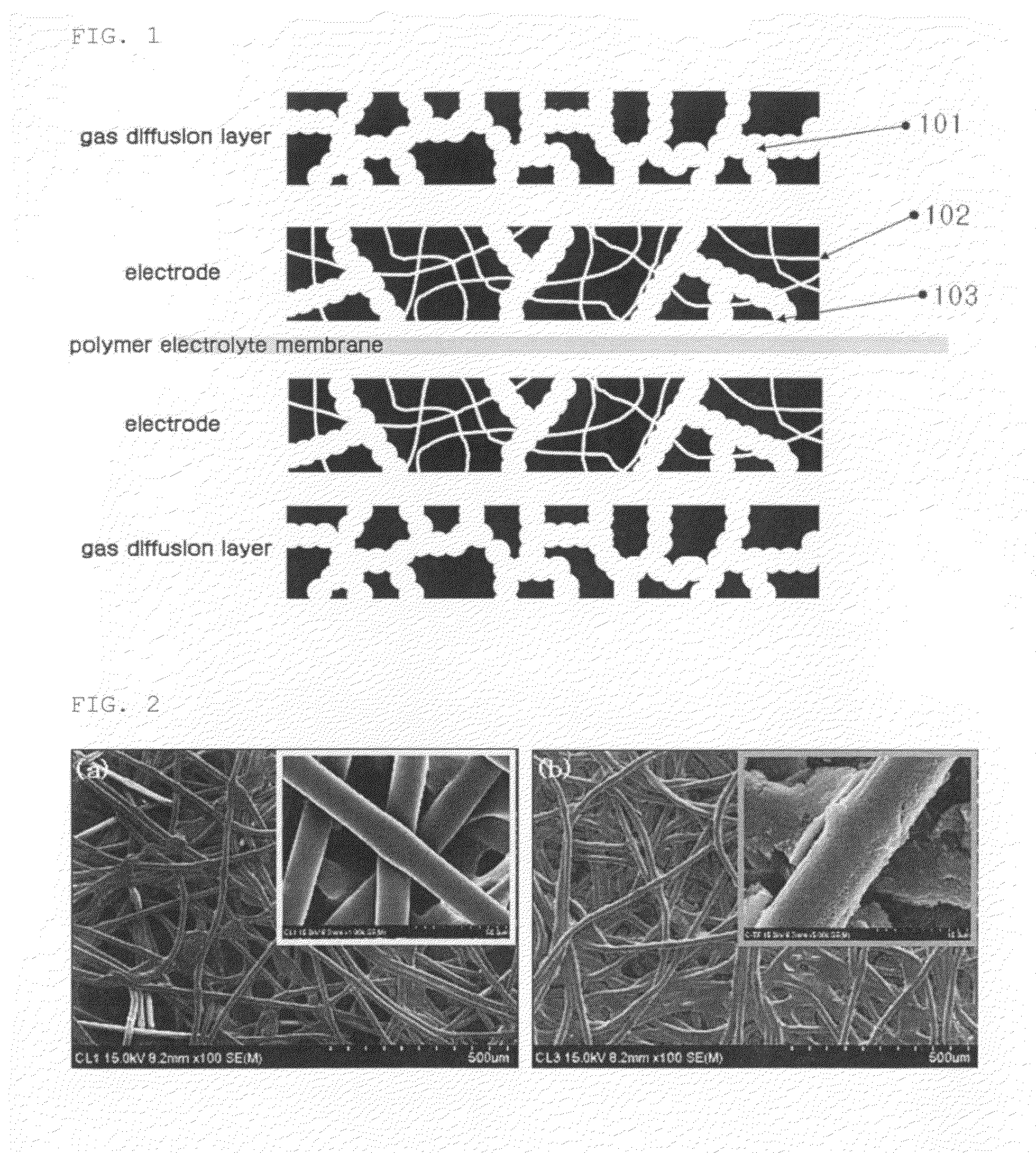
[0039]A non-conductive porous substrate (mixture of viscose rayon / polyester (DuPont Company, Name of Product: Sontara), 85% porosity, average pore size 4 μm) having a thickness of 20 μm is put on a spray coating device of whose lower plate is heated at 70° C. and its both sides are coated with the pre...

example 2

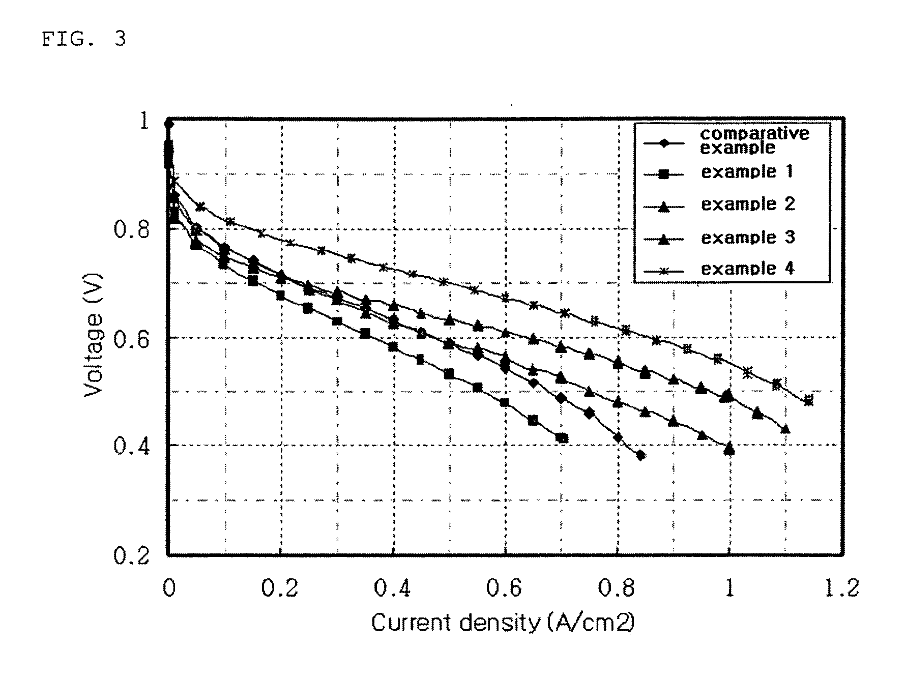
[0042]A membrane-electrode assembly is prepared in the same manner as that shown in the example 1 and then a unit cell is engaged. However, a porous substrate having a thickness of 5 μm is used.

example 3

[0043]A membrane-electrode assembly is prepared in the same manner as that shown in the example 1 and then a unit cell is engaged. However, a porous substrate having a thickness of 10 μm is used.


PUM

PropertyMeasurementUnit
porosityaaaaaaaaaa
thicknessaaaaaaaaaa
mean secondary particle diameteraaaaaaaaaa

Abstract

The present invention relates to a porous electrode used in a polymer electrolyte membrane fuel cell, and more particularly to a method of preparing a membrane-electrode assembly by forming a self-stand electrode layer by coating catalyst ink on a non-conductive substrate having a macropore and then joining it to a polymer electrolyte membrane. The porous self-stand electrode according to the present invention allows moisture and gas to be smoothly discharged and inflowed in a high current density operation region to improve the performance of a fuel cell, and can be freely cutted to simplify the preparation process of the membrane-electrode assembly.

Description

TECHNICAL FIELD[0001]The present invention relates to a porous electrode used in a polymer electrolyte membrane fuel cell, and more particularly to a method of preparing a membrane-electrode assembly by forming a self-stand electrode layer by coating catalyst ink on a non-conductive substrate having a macropore and then joining it to a polymer electrolyte membrane. The porous self-stand electrode according to the present invention allows moisture and gas to be smoothly discharged and inflowed in a high current density operation region to improve the performance of a fuel cell, and can be freely cutted to simplify the preparation process of the membrane-electrode assembly.BACKGROUND ART[0002]A fuel cell is a device that directly converts chemical energy of fuel into electric energy by electrochemically reacting fuel such as hydrogen or methanol with oxygen, does not go through a carnot cycle differently from the existing thermal power generation, such that the fuel cell has high powe...

Claims


Application Information

Patent Timeline
Patent Type & Authority Applications(United States)
IPC IPC(8): H01M8/10H01M4/86H01M8/00
CPCH01M4/8828H01M8/1004Y10T29/49108Y02E60/522H01M2008/1095Y02E60/50Y02P70/50H01M4/86H01M4/88H01M4/90
Inventor KIM, YOUNG TAEKSEO, MIN-HOJANG, BYUNGCHULRYU, DONG HWANYANG, JUNG-EUNJIONG, YOUNGSU
Owner HANWHA CHEMICAL CORPORATION
Why Eureka
Try Eureka