Supercharge Your Innovation With Domain-Expert AI Agents!

Plasma reactor and plasma reaction apparatus

a reactor and plasma technology, applied in plasma technology, machines/engines, plasma production, etc., can solve the problems of high heat resistance and high cost of precious metal catalysts, and achieve the effect of suppressing catalyst deterioration and reducing reaction temperatur

Inactive Publication Date: 2009-08-20
NGK INSULATORS LTD
View PDF7 Cites 3 Cited by
  • Summary
  • Abstract
  • Description
  • Claims
  • Application Information

AI Technical Summary

Benefits of technology

[0007]Therefore, technology that more efficiently produces gas by utilizing a plasma reaction, a catalytic reaction, and the like has been desired. An object of the present invention is to provide a plasma reactor that can efficiently process gas by utilizing plasma, and a plasma reaction apparatus.
[0026]Since the plasma reactor according to the present invention includes the honeycomb electrode that includes the first gas circulation section that allows the first gas to pass through and the second gas circulation section that allows the second gas to pass through, and a discharge electrode that is disposed to face the honeycomb electrode and allows a plasma discharge to occur between the discharge electrode and the honeycomb electrode so that the first gas undergoes a reaction, the first gas can be introduced into the first gas circulation section of the honeycomb electrode through the space between the electrodes to undergo a reaction while causing a plasma discharge between the honeycomb electrode and the discharge electrode, and the second gas can be introduced into the second gas circulation section of the honeycomb electrode to transfer heat of the second gas to the first gas circulation section to promote the reaction of the first gas. Moreover, the reaction temperature can be reduced so that catalyst deterioration can be suppressed.

Problems solved by technology

The catalyst quickly deteriorates when the processing target gas is heated to such a high temperature.
This makes it necessary to use a large amount of expensive precious metal catalyst having high heat resistance.

Method used


Image

  • Plasma reactor and plasma reaction apparatus
  • Plasma reactor and plasma reaction apparatus
  • Plasma reactor and plasma reaction apparatus

Examples


example 1

[0070]Production of counter-flow heat exchanger-integrated hybrid honeycomb reactor

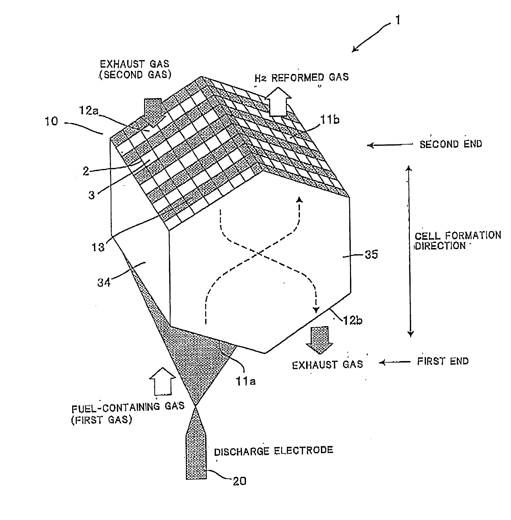
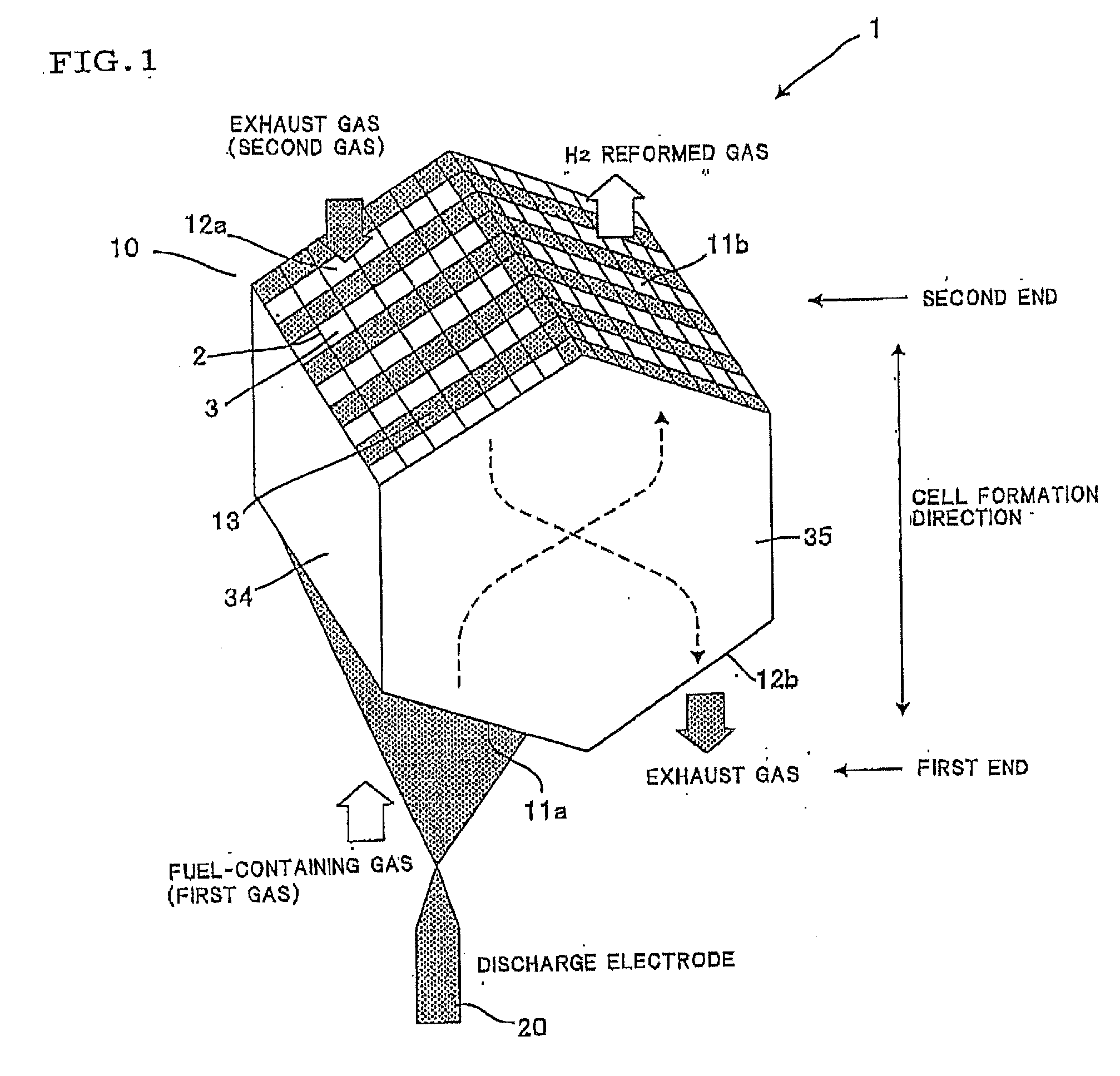
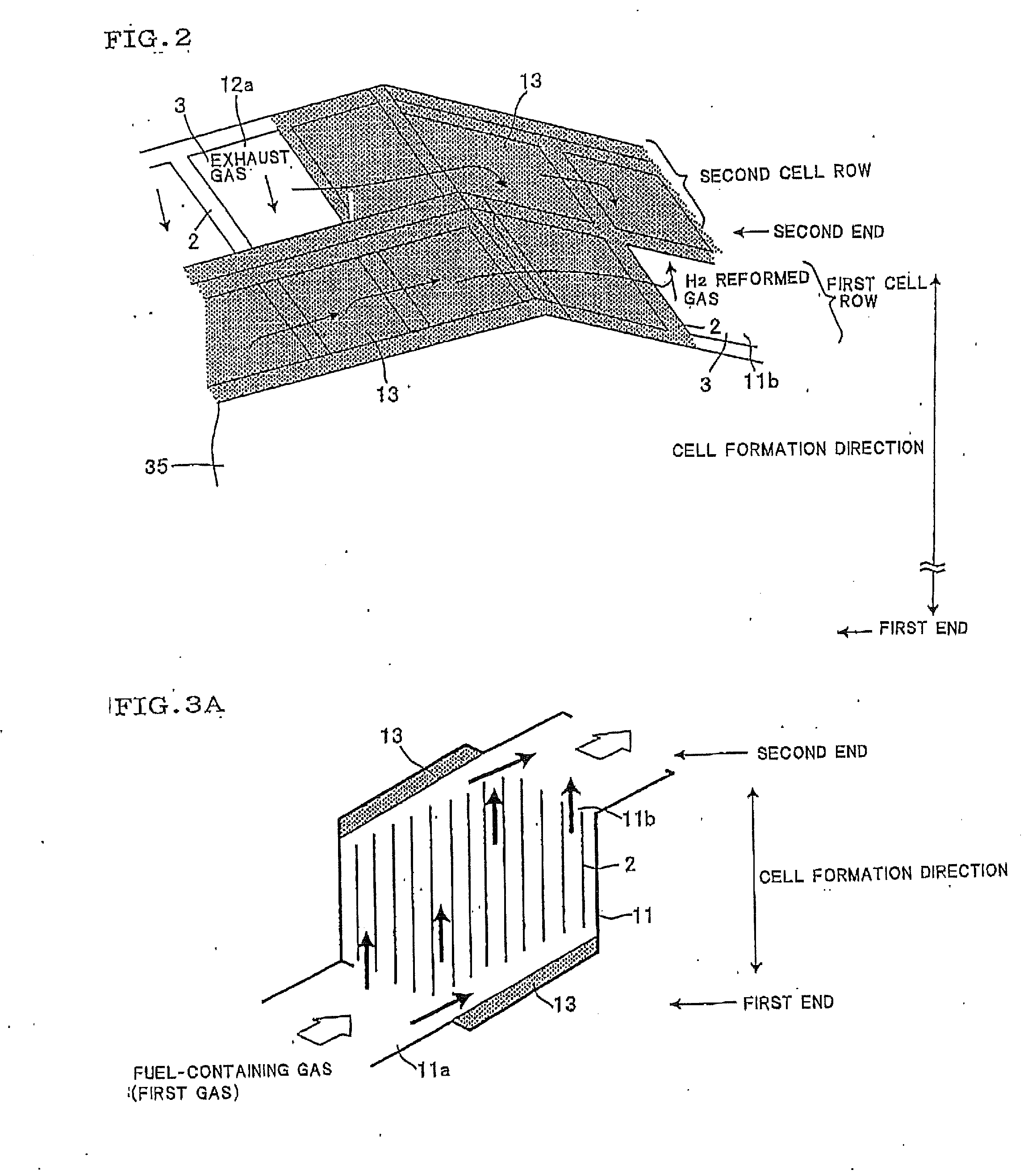
[0071]A quadrangular prism-shaped honeycomb structure formed of silicon carbide (SiC) was cut in the shape of a hexagon (side length: 20 ma) (see FIG. 5). The left side of the first end (see FIG. 1) was removed by 5 mm at intervals of one cell (see FIG. 7). The groove was plugged with a plugging material to a depth of about 1.5 to 2 mm (see FIG. 6). The right side of the first end (see FIG. 1) was removed by 5 mm corresponding to the cells different from those of the left side of the first end. The groove was plugged with a plugging material to a depth of about 1.5 to 2 mm. The left side of the second end (see FIG. 1) was removed by 5 mm corresponding to the same cells as those of the right side of the first end. The groove was plugged with a plugging material to a depth of about 1.5 to 2 mm. The right side of the second end (see FIG. 1) was removed by 5 mm corresponding to the cells different from th...

example 2

[0072]Production of counter-flow heat exchanger-integrated catalyst-supporting hybrid honeycomb reactor

[0073]Alumina fine powder (specific surface area: 107 m2 / g) was impregnated with a nickel nitrate (Ni(NO:3)2) solution, dried at 120° C., and fired at 550° C. for three hours in air to obtain Ni / alumina powder containing nickel (Ni) in an amount of 10 mass % based on alumina. After the addition of alumina sol and water to the Ni / alumina powder, the pH of the mixture was adjusted to 4.0 using a nitric acid solution to obtain a slurry. A honeycomb electrode 10 similar to that of Example 1 was immersed in the slurry, dried at 120° C., and fired at 550° C. for one hour in a nitrogen atmosphere to obtain a counter-flow heat exchanger-integrated catalyst-supporting hybrid honeycomb reactor (plasma reactor 1). In the examples, the plasma reactor 1 was used as a negative electrode. The amount of Ni supported on the plasma reactor 1 was 25 g / l.

[0074]A plasma generation power supply (pulse p...


PUM

PropertyMeasurementUnit
Timeaaaaaaaaaa
Lengthaaaaaaaaaa
Shapeaaaaaaaaaa

Abstract

A plasma reactor includes a honeycomb electrode in which a plurality of cells that function as gas passages are partitioned by a partition wall, and a discharge electrode. The honeycomb electrode includes a first gas circulation section that allows a first gas to pass through, and a second gas circulation section that allows a second gas to pass through. The plasma reactor causes the first gas introduced into the first gas circulation section of the honeycomb electrode through the space between the electrodes to undergo a reaction while causing a plasma discharge between the honeycomb electrode and the discharge electrode, and allows the second gas to be introduced into the second gas circulation section of the honeycomb electrode to transfer heat of the second gas to the first gas circulation section to promote the reaction of the first gas.

Description

BACKGROUND OF THE INVENTION[0001]1. Field of the Invention[0002]The present invention relates to a plasma reactor that includes a reaction section that allows gas introduced into a honeycomb structure to undergo a reaction by generating plasma, and a heat-supplying gas circulation section, and a plasma reaction apparatus.[0003]2. Description of Related Art[0004]A silent discharge occurs when disposing a dielectric between a pair of tabular electrodes and applying a high alternating-current voltage or a periodic pulse voltage between the electrodes. Active species, radicals, and ions are produced in the resulting plasma field to promote a reaction and decomposition of gas. This phenomenon may be utilized to remove toxic components contained in engine exhaust gas or incinerator exhaust gas.[0005]Technology that mixes hydrocarbon fuel and air, reforms the mixture using a catalyst, and supplies a reformed gas containing hydrogen to an internal combustion engine has been known (see JP-A-...

Claims


Application Information

Patent Timeline
IPC IPC(8): H01J37/02
CPCB01D53/32B01D2259/818B01J19/088B01J19/2485B01J2219/0824B01J2219/0843Y02T10/16C01B3/38C01B2203/0227C01B2203/0861F01N5/02H05H2001/4697H05H2245/1215B28B11/006Y02P20/52Y02T10/12H05H1/4697H05H2245/17
Inventor MASUDA, MASAAKITAKAHASHI, MICHIOMIZUNO, HIROSHI
Owner NGK INSULATORS LTD
Features
  • R&D
  • Intellectual Property
  • Life Sciences
  • Materials
  • Tech Scout
  • Unparalleled Data Quality
  • Higher Quality Content
  • 60% Fewer Hallucinations
Learn More