Noise reduction systems and methods

a technology of noise reduction and noise reduction, applied in the direction of automatic control, process and machine control, instruments, etc., to achieve the effect of reducing common-mode nois

Active Publication Date: 2009-08-27
POWER INTEGRATIONS INC
View PDF10 Cites 27 Cited by
  • Summary
  • Abstract
  • Description
  • Claims
  • Application Information

AI Technical Summary

Benefits of technology

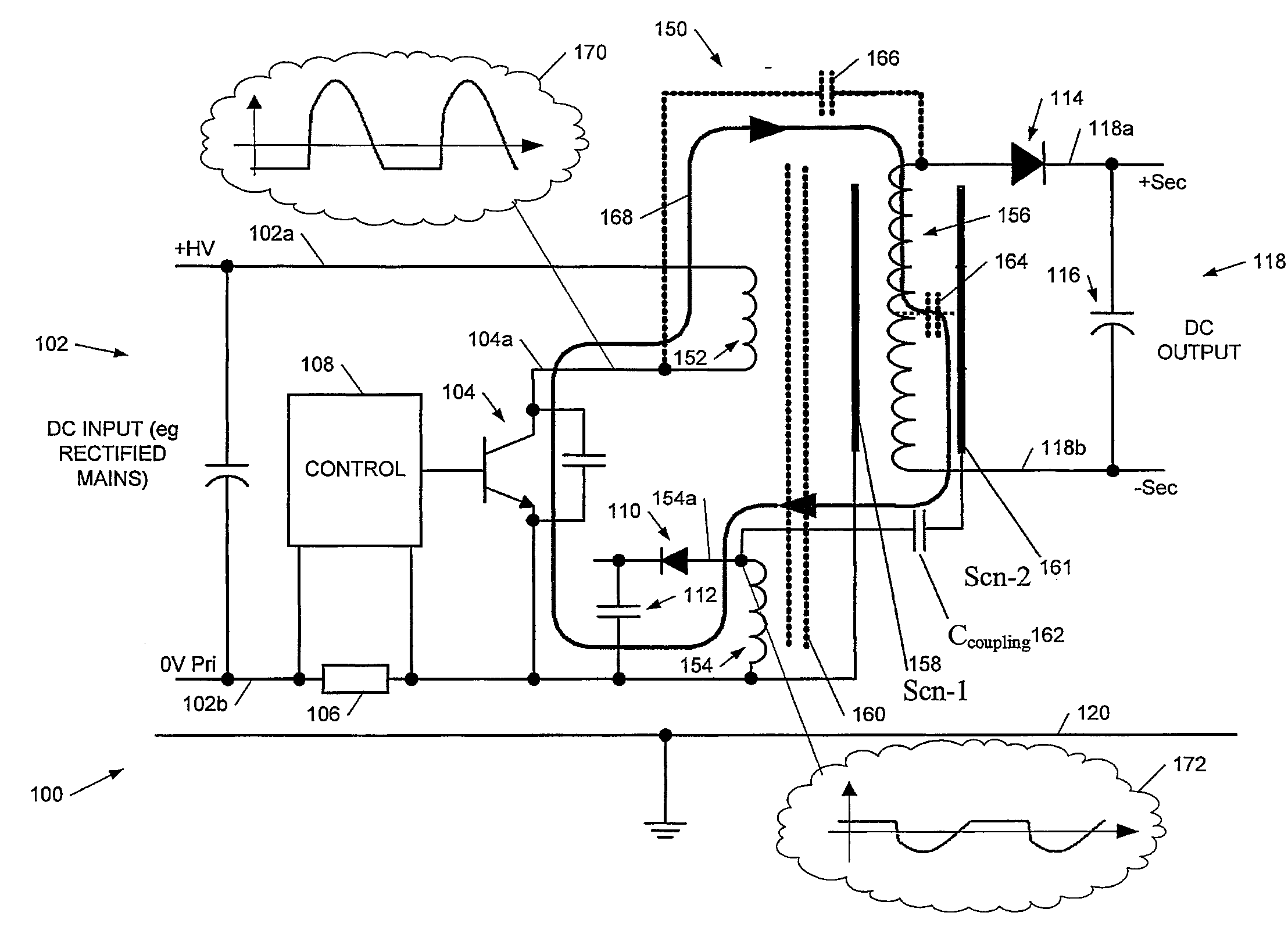
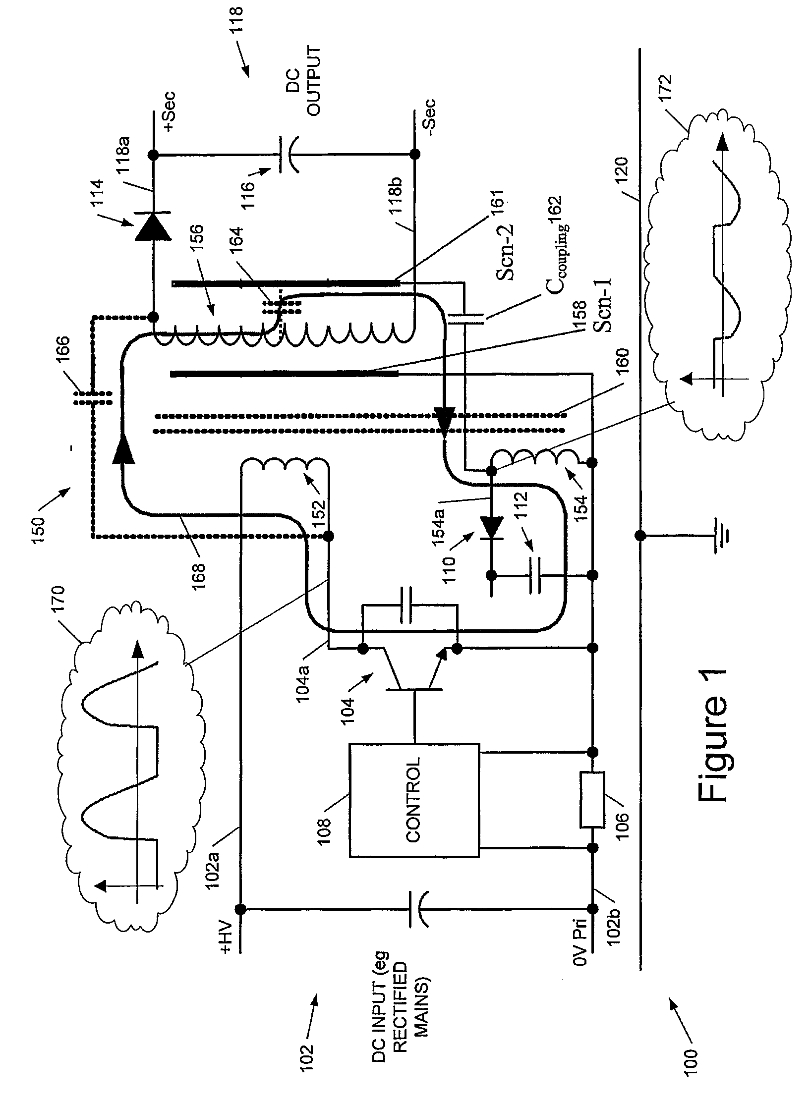
[0022]According to the present invention there is therefore provided a method of reducing common-mode noise from unshielded coupling in a switch mode power supply; said switch mode power supply having a power input, a switch, a transformer, and a power output; said transformer having at least a primary winding on a primary side of said power supply and coupled to said power input via said switch, and a secondary winding of said transformer on a secondary side of said power supply and coupled to said power output; said noise from unshielded coupling comprising a noise voltage on a second of said windings coupled fro...

Problems solved by technology

Common mode noise propagation between primary and electrically-isolated secondary circuits in Switch Mode Power Supplies (SMPSs) has long been a problem.
Such noise is also radiated and may adversely affect any sensitive nearby components and circuits.
However, even if multiple shields are connected to primary and secondary circuits, some residual noise signal remains.
Such additional structures typically add cost and bulk to the transformer, and may degrade other performance factors such as leakage inductance.
Furthermore, optimisation of such structures for effective cancellation is often not straightforward.2. Adaptations to transformer structures, such as matching voltage gradients in adjacent primary and secondary coil layers (see, for example, U.S. Pat. No. 5,107,411 Philips).
These techniques tend to offer only modest improvements in noise rejection, and are difficult to optimise.3. Partial coupling of inverse phase noise signals to the secondary winding:a) Using an amplifier connected to both primary and secondary circuits to generate a counteracting noise voltage, which cancels the residual noise voltage (see, for example, U.S. Pat. No. 6,879,500 University of Hong Kong).b) Using an auxilia...

Method used


Image

  • Noise reduction systems and methods
  • Noise reduction systems and methods
  • Noise reduction systems and methods

Examples


Embodiment Construction

[0041]We will describe preferred embodiments of the invention implemented in switching power converters where the output is galvanically isolated from the power input. A common application is mains-powered low voltage DC supplies. Switching noise voltages caused by the power switch (or switches) can cause common-mode noise by capacitive coupling between the switching (input) circuits and the isolated output circuits. Embodiments of the invention can be applied to a wide variety of converter topologies including, but not limited to, flyback and forward converters.

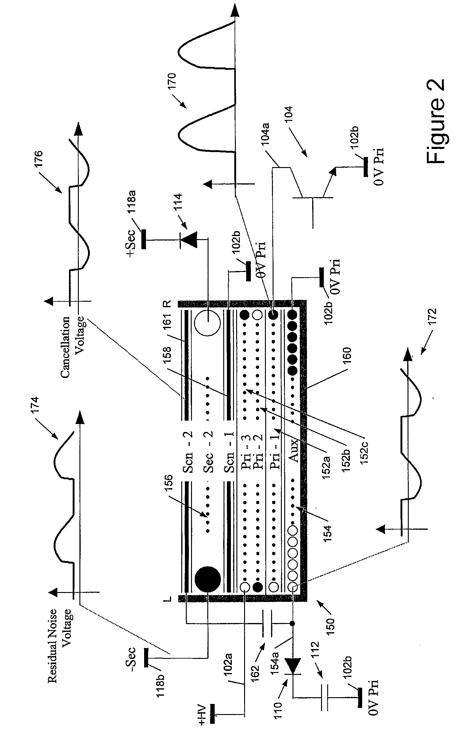
[0042]Broadly speaking, embodiments of the present invention apply a cancellation signal to any convenient structure(s) other than a main inter-winding screen that is (are) capacitively coupled to the secondary winding, preferably in addition to such a main inter-winding screen. Examples include the transformer core itself and / or the flux band or another conductive shield associated with the secondary winding. We shall refer...


PUM


Abstract

We describe a switch mode power supply having a power input, a switch, a transformer, and a power output. The transformer has a primary winding coupled to said power input via said switch, and a secondary winding coupled to said power output. The transformer further comprises an auxiliary winding and a coupling structure capacitatively coupled to said secondary winding of said transformer; wherein said coupling structure does not comprise a shield or screen between said primary and secondary windings. The switch mode power supply further comprises a coupling capacitor connected between said coupling structure and said auxiliary winding to provide a noise suppression voltage from said auxiliary winding to said secondary winding to at least partially cancel a common mode noise voltage on said secondary winding from unshielded coupling from said primary winding.

Description

RELATED APPLICATION[0001]This application claims priority under 35 U.S.C. 119 to United Kingdom Application No. 0803183.3, filed Feb. 21, 2008, which application is incorporated herein by reference and made a part hereof.FIELD OF THE INVENTION[0002]This invention relates to methods of reducing noise emissions or electromagnetic interference (EMI) in switch mode power supplies, and to switch mode power supplies embodying such techniques.BACKGROUND TO THE INVENTION[0003]Common mode noise propagation between primary and electrically-isolated secondary circuits in Switch Mode Power Supplies (SMPSs) has long been a problem. High frequency noise, or Electro-Magnetic Interference (EMI), generated by the switching transistor(s) in the primary circuit and the rectifier(s) in the secondary circuit are conducted, via primary-secondary stray capacitances, either back to the line supplying the SMPS, or into the load that it is powering. Such noise is also radiated and may adversely affect any se...

Claims


Application Information

Patent Timeline
IPC IPC(8): G05F1/46
CPCH02M1/14H02M7/003H02M3/335H02M1/44H02M1/126
Inventor RYAN, PAULLEISTEN, JOE MICHAEL
Owner POWER INTEGRATIONS INC
Why Eureka
Try Eureka