
Advanced Materials for Regenerative Pyrolysis Reactors, Methods, and Reactors Using the Same

a technology of advanced materials and pyrolysis reactors, applied in the direction of metal/metal-oxide/metal-hydroxide catalysts, liquid-gas reaction processes, hydrocarbon by hydrocarbon cracking, etc., can solve the problems of high cost, specialty production, and the inefficiency of known processes, so as to improve certain properties or uses

Active Publication Date: 2009-10-08
EXXONMOBIL CHEM PAT INC
View PDF12 Cites 26 Cited by
  • Summary
  • Abstract
  • Description
  • Claims
  • Application Information

AI Technical Summary

Benefits of technology

[0025]It is also preferred that the SRZ comprises a modulus of rupture (MOR) mechanical flexural strength of not less than 2 kpsi (13.8 MPa) prior to firing the SRZ-laden reactor or otherwise initially heating the SRZ material to a temperature of at least 1000° C. More preferably, it is preferred that the SRZ comprises a MOR mechanical flexural strength of not less than 2 kpsi (13.8 MPa) when the reactor is fired or otherwise heated to a temperature in a range of from 1000° C. to 1800° C. Still more preferably, it may be preferred that the SRZ comprises a MOR mechanical flexural strength of not less than 2 kpsi (13.8 MPa) when the reactor is fired or otherwise heated to a temperature in a range of from 1000° C. to 2000° C.
[0026]Many preferred apparatus according to the present invention may also include an SRZ that comprises an MOR mechanical flexural strength measured at 50° C. after water bath quenching from a temperature in a range of from 1000° C. to 1800° C. that is at least 70% of said stabilized refractory grade zirconia's MOR flexural strength measured at a temperature in a range of from 1000° C. to 1800° C. The procedure used is as described in ASTM C 1525-4. Still more preferred embodiment may include an SRZ that comprises an MOR mechanical flexural strength measured at 50° C. after water-bath quenching from a temperature in a range of from 1000° C. to 1800° C. that is at least 80% of said stabilized refractory grade zirconia's MOR flexural strength measured at a temperature in a range of from 1000° C. to 1800° C.
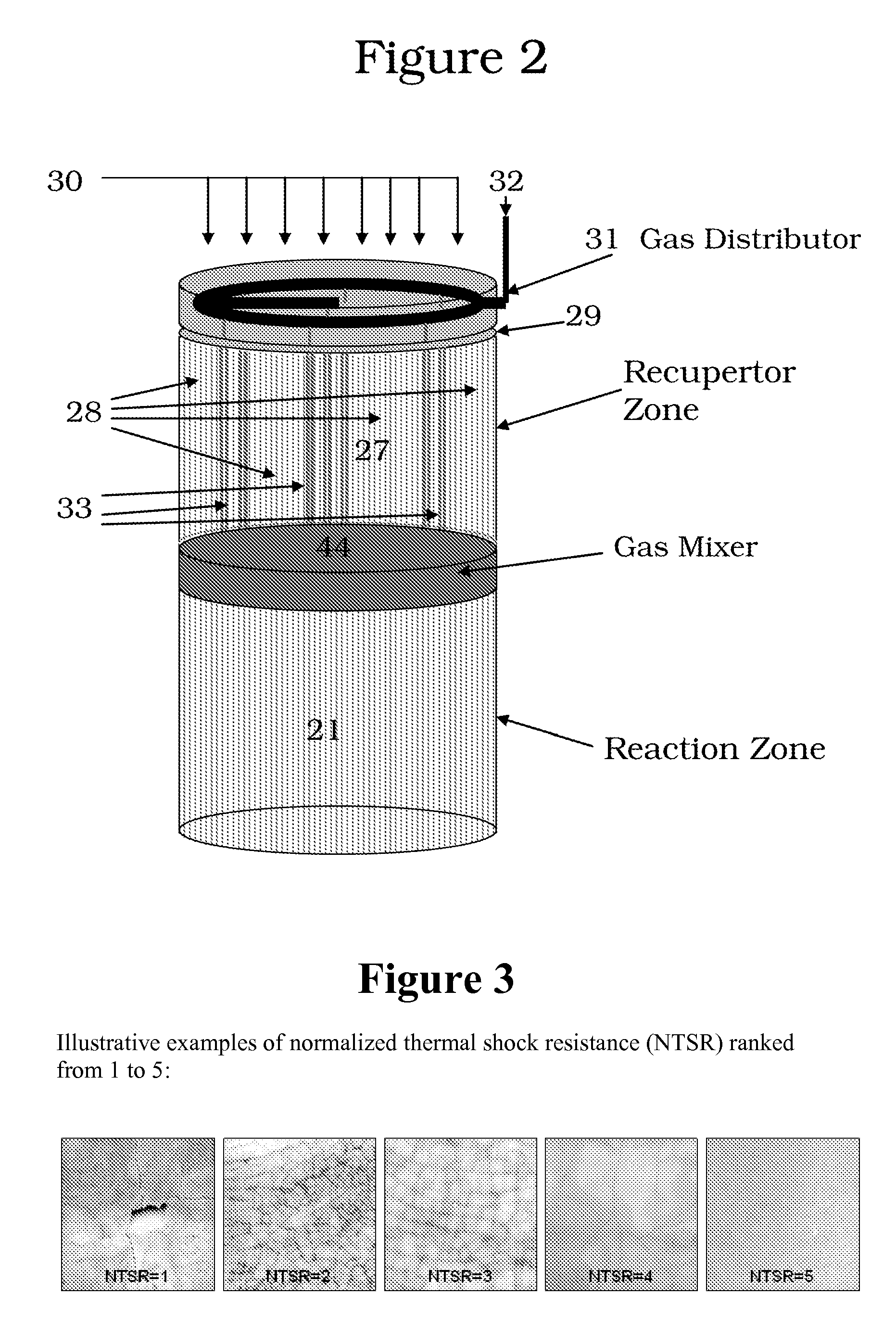
[0027]In most preferred embodiments, the SRZ is stabilized by at least one stabilization component that includes at least one of CaO, MgO, Y2O3, CeO2, and mixtures thereof. Preferably, the SRZ comprises at least one weight percent of the stabilization component, based upon the total weight of said stabilized refractory grade zirconia. In other embodiments, the SRZ further comprises one or more secondary oxides selected from the group consisting of Al, Si, Mg, Ca, Y Fe, Mn, Ni, Co, Cr, Ti, Hf, V, Nb, Ta, Mo, W, Sc, La, and Ce, and mixtures thereof. Secondary oxides may be merely incidentally present or may be purposefully added such as to improve certain properties or uses, e.g., such as processability during manufacture. In many preferred embodiments, the SRZ is a partially stabilized zirconia (PSRZ). Preferred PSRZ, including PSRZ, may include a thermal shock resistance rating that demonstrates a total crack length per unit area after quenching a test specimen of said stabilized refractory grade zirconia at 1100° C. into a water bath at room temperature that is not greater than 5 cm / cm2. Preferably, the partially stabilized refractory grade zirconia comprises a modulus of rupture (MOR) mechanical flexural strength of not less than 4 kpsi (27.6 MPa) when heated to a temperature in a range of from 1000° C. to 1800° C. It is also preferred that the PSRZ comprises a MOR mechanical flexural strength measured at 50° C. after quenching from a temperature in a range of from 1000° C. to 1800° C. that is at least 80% of said PSRZ's MOR flexural strength measured at a temperature in a range of from 1000° C. to 1800° C.
[0028]In most preferred embodiments, the stabilized refractory grade zirconia is stabilized by at least one stabilization component that includes at least one of CaO, MgO, Y2O3, CeO2, and mixtures thereof. Preferably, the SRZ comprises at least one weight percent of the stabilization component, based upon the total weight of said stabilized refractory grade zirconia. In other embodiments, the SRZ further comprises one or more secondary oxides selected from the group consisting of Al, Si, Mg, Ca, Y Fe, Mn, Ni, Co, Cr, Ti, Hf, V, Nb, Ta, Mo, W, Sc, La, and Ce, and mixtures thereof.
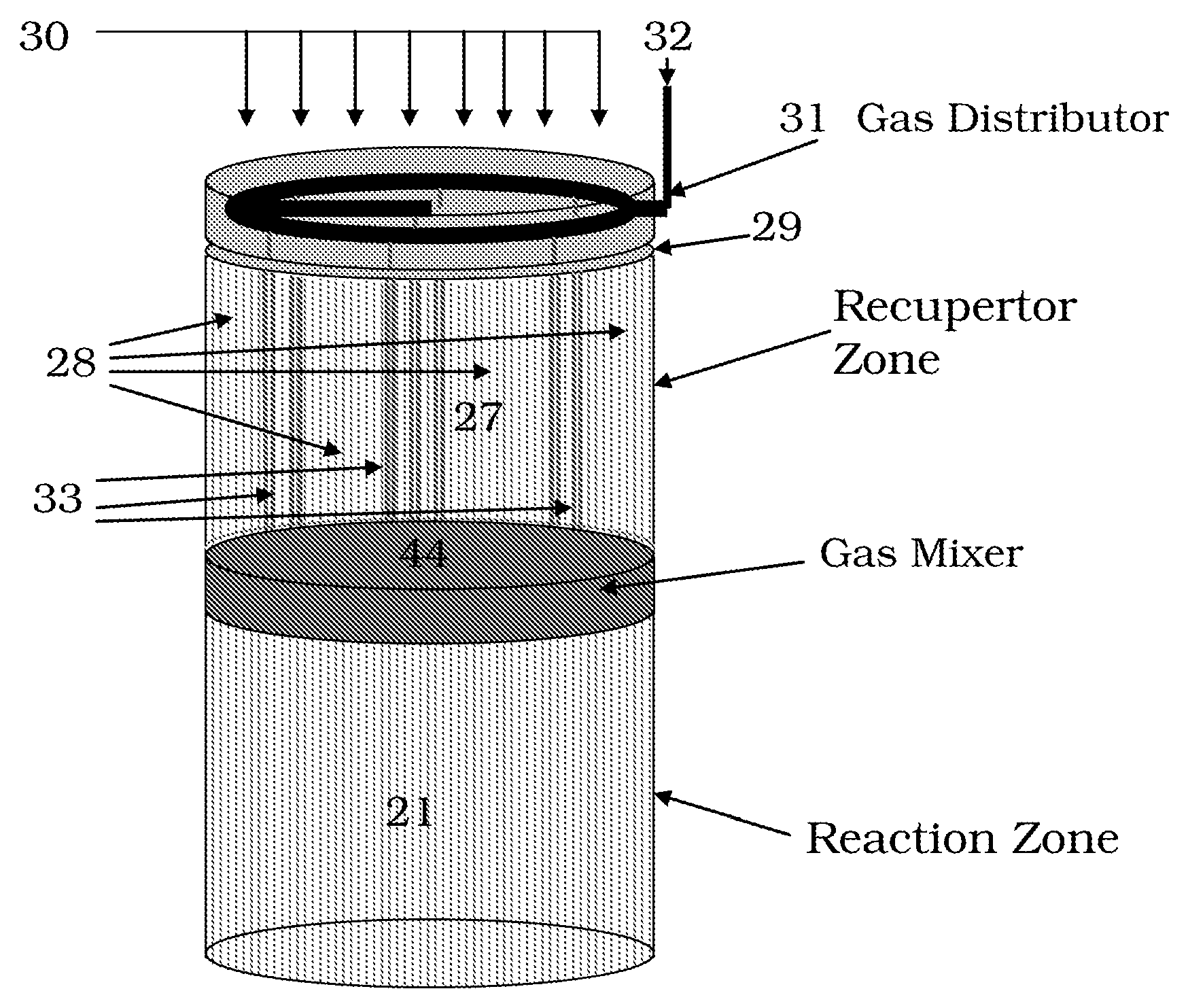
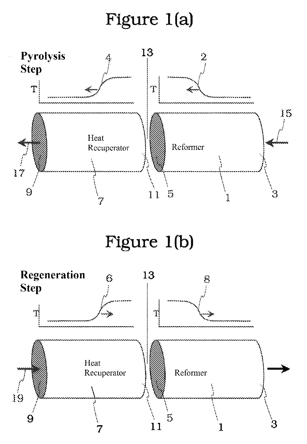
[0029]In another aspect, the invention includes a reverse flow regenerative pyrolysis reactor system comprising a first reactor and a second reactor in flow communication with the first reactor, the first reactor comprising a first channel for conveying a first reactant through the first reactor to the second reactor and a second channel for conveying a second reactant through the first reactor to the second reactor, the first reactant exothermically reacting with the second reactant, in or proximate to the second reactor, wherein the second reactor comprises a SRZ, more preferably the SRZ is a PSRZ. Preferably, at least the first reactor comprises SRZ, and more preferably both reactors comprise the SRZ, particularly in the portions of the reactor bed that are subjected to the extremely high temperatures or to the extremely high temperature swings experienced during the cyclic reactor operation. In some preferred embodiments, the reactor system further comprises a reactant mixer intermediate the first and second reactors for combining or mixing at least a portion of the first reactant with at least a portion of the second reactant, wherein the reactant mixer comprises SRZ, and more preferably PSRZ. The mixer may be either a component that is separate from the first and / or second reactors or may be an integral portion or component of either or both of the first or second reactor that is proximate the other of the first or second reactor.
[0030]In still another aspect, the invention includes a method for pyrolyzing a hydrocarbon feedstock using a regenerative pyrolysis reactor, preferably a reverse flow regenerative pyrolysis reactor, comprising the steps of providing a regenerative pyrolysis reactor including a stabilized refractory grade zirconia, more preferably a PSRZ, in a reactive region or heated reaction zone of the reactor, and pyrolyzing a hydrocarbon feedstock within the heated reaction zone. Preferably, the method further comprises the step of heating the heated reaction zone by a deferred combustion process. In some preferred embodiments, the method includes use of a reactant mixer in or near the reaction zone, such as between the first and second reactors, for combining or mixing at least a portion of the first reactant with at least a portion of the second reactant, wherein the reactant mixer comprises PSRZ.

Problems solved by technology

Acetylene (or ethyne, HC≡CH) has long been recognized as one of the few compounds that can be made directly at high selectivity from methane pyrolysis but the conditions of that manufacture have placed it beyond commercial practicality for other than high cost, specialty production.
One of the biggest impediments to producing acetylene from methane or other hydrocarbon feeds has been the very high temperatures required to produce high-yield conversion of methane to acetylene.
Pyrolyzing large quantities of methane into acetylene for conversion to olefins had been considered too costly and impractical due to the special types and costs of equipment that would be required.
However the known processes are inefficient compared to commercial steam cracking, do not scale well, and are generally only useful for specialty applications.
Such temperature and processes have largely been unattractive due to thermal, chemical, and mechanical degradation of the equipment utilized.
Virtually any metal components directly exposed to such temperatures and stress due to cyclical temperature fluctuations, will be costly and unacceptably degrade over time.
Although regenerative pyrolysis reactors are generally known in the art as capable of converting or cracking hydrocarbons, they have not achieved commercial or widespread use, due at least in part to the fact that they have not been successfully scaled well to a commercially economical size or commercially useful life span.
These drawbacks to wide scale commercialization are due in large part to the inability of the equipment to adequately control and contend with the very high temperatures.
A related challenge has been in controlling how fuel and oxidant are combined during the regeneration or heating stage of the process.
Inability to effectively control this issue contributes to the degradation of components and inefficiency at commercial scale.
Due to uncontrolled exothermic reaction, the created high temperatures are difficult to position and contain for extended periods of time and lead to premature equipment failure.
Another challenge relates to materials stability at high temperature.
Many prior art reactor materials undergo or become susceptible to chemistry alterations at the high process temperatures.
The alterations lead to premature equipment degradation and potentially even interference with the process chemistry.
Complicating the issue still further for regenerative or cyclic reverse flow reactors has been the detrimental effects upon materials that are exposed to the large, cyclic temperature swings encountered during the process.
Unfortunately, these economically favored feedstocks typically contain undesirable amounts of nonvolatile components and have heretofore been unacceptable as regenerative reactor feedstocks.
Regenerative pyrolysis reactors do not have the flexibility to process such otherwise economically crack favorable feedstocks because, although coke can typically be burned off, deposits or buildup of ash and metals within the reactor cannot easily be burned or removed.
This publication indicates that the use of these furnaces permits substantial increases in the yield of olefins (i.e., ethylene, propylene, butadiene) while decreasing production of less-desirable co-products.
It is believed that all commercial acetylene plants operated on feeds of ethane, naphtha, and / or butane, but that none have successfully operated on methane feeds.
However, the lateral introduction also exposes the lateral injection nozzles or ports to the combustion product, including the extremely high temperature needed to crack methane feeds.
Degradation in nozzle performance, shape, and / or size consequently made it extremely difficult to control flame shape, temperature, and efficiency.
Although some of the Wulff art disclose use of various refractory materials, a commercially useful process for methane cracking was not achieved utilizing such materials.
Also, a further and more significant drawback of the Wulff process is that the laterally or separately introduced portion of exothermic reactant is not utilized for quenching the recuperation reactor bed.
This imbalance in heat created and heat removed typically results in an expanding heat gradient through the reactor bed and corresponding changes in reaction timing, duration, and control.
This situation creates significant difficulty with quenching the reaction at precisely the right time to produce the desired acetylene or other reaction product.
The aforementioned practical obstacles have impeded large scale implementation of the technologies.
Materials availability for such high temperature is one of the most critical issues in design and operation of large-scale, commercial, high-productivity, RFR's.
Even though engineering grade ceramics have superior strength and toughness at relatively low temperatures, they are relatively poor in thermal shock resistance and many grades, such as but not limited to borides, carbides, and nitrides are not chemically stable at high temperature.
Many are also not suitable for use at the high temperatures encountered with some pyrolysis reactions.
However, insulation grade ceramics usually lack the structural strength and functional toughness needed for the internal components of RFR's that are directly exposed to the pyrolysis reactions and flowing, hot reactants or products.
Also, the insulation properties of porous ceramics may also tend to degrade over time as the relatively large pores may tend to fill with coke accumulation.
However, while some refractory grade ceramics tend to be somewhat inert or chemically stable at elevated temperatures, some refractory grade ceramics become chemically and / or structurally unstable at elevated temperatures, rendering them unsuitable for applications exposed to chemical reactions.
Such alterations can result in changes in bulk volume which can result in production of stress fractures and / or cleavage planes which can reduce the material's strength.
However, the studied art does not teach preferred crystalline structure or composition for particular reactor furnace uses.
The reviewed art is also void of teaching how to prepare or select a material having a range of properties that are suitable for use in constructing a furnace for performing substantially continuous, cyclical, high temperature pyrolysis chemistry.
Also, materials testing methods commonly applied to metals and polymers are frequently less useful for testing ceramics.
The available tests provide only a limited picture of the total performance limits of any particular ceramic.
These sparse, non-specific disclosures left the art largely incapable of providing a large-scale, commercially useful reactor or reactor process.
The teachings of the art was only effective for enabling relatively small scale specialty applications that see vastly inferior use as compared to large scale processes such as hydrocarbon steam cracking.
Lack of materials availability and selection criteria for identifying the materials for use in the reactive and most severe temperature regions of a reactor system is one of the most critical remaining issues in design and large-scale operation of such reactors.

Method used


Image

  • Advanced Materials for Regenerative Pyrolysis Reactors, Methods, and Reactors Using the Same
  • Advanced Materials for Regenerative Pyrolysis Reactors, Methods, and Reactors Using the Same
  • Advanced Materials for Regenerative Pyrolysis Reactors, Methods, and Reactors Using the Same

Examples


Embodiment Construction

[0034]Zirconia is a crystalline material that undergoes a change at different temperatures in the way its atoms are stacked (polymorphic transformation). Zirconia has a monoclinic crystal structure between room temperature and about 950° C. Above about 950° C., zirconia converts to the tetragonal crystal structure. This transformation is accompanied by greater than one percent volumetric shrinkage during heating and equivalent expansion during cooling. At a still higher temperature, the zirconia changes from tetragonal to a cubic structure. These volumetric changes associated with alterations in crystalline structure can produce crystalline fractures or cleavages along grain boundaries. In pure polycrystalline zirconia, this tetragonal-monoclinic transition results in a reduction in strength and potential catastrophic failure of the component.

[0035]Chemical addition of at least one mole percent of one or more of CaO, MgO, Y2O3, CeO2 or mixtures thereof to the zirconia, based upon th...


PUM


Abstract

In one aspect, the invention includes an apparatus for pyrolyzing a hydrocarbon feedstock in a regenerative pyrolysis reactor system, the apparatus comprising a regenerative pyrolysis reactor comprising a stabilized refractory grade zirconia in a reactive region of the reactor system. In another aspect, this invention includes a method for pyrolyzing a hydrocarbon feedstock using a reverse flow regenerative pyrolysis reactor comprising the steps of providing a reverse flow regenerative pyrolysis reactor including a stabilized refractory grade zirconia in a heated reaction zone of the reactor; and pyrolyzing a hydrocarbon feedstock within the reactive region.

Description

FIELD OF THE INVENTION[0001]This invention pertains to materials, methods, and apparatus useful in regenerative pyrolysis reactors such as may be used for thermally converting hydrocarbons. The invention relates to materials, apparatus, and methods for cracking hydrocarbon feedstocks in a high-severity, regenerative pyrolysis reactor. More particularly, the invention relates to reactor materials that facilitate improved process reliability and equipment durability.BACKGROUND OF THE INVENTION[0002]Conventional steam crackers are an effective tool for cracking high-quality feedstocks that contain a large fraction of volatile hydrocarbons, such as ethane, propane, naphtha, and gas oil. Similarly, regenerative pyrolysis reactors, including reverse flow pyrolysis reactors (“RFR”), are also used for converting or cracking hydrocarbons and to execute cyclic, high temperature chemistry such as those reactions that may be performed at temperatures higher than can suitably be performed in con...

Claims


Application Information

Patent Timeline
Patent Type & Authority Applications(United States)
IPC IPC(8): C10G11/00B01J19/00
CPCB01J8/0438C04B2235/96B01J19/2485C07C4/04B01J8/0442C04B2235/77C04B35/486C04B2235/3206C04B2235/3208C04B2235/3217C04B2235/3224C04B2235/3227C04B2235/3229C04B2235/3232C04B2235/3239C04B2235/3251C04B2235/3256C04B2235/3258C04B2235/3262C04B2235/3272C04B2235/3275C04B2235/3279C04B2235/3418C04B2235/72C04B2235/76C07C11/24
Inventor CHUN, CHANGMINHERSHKOWITZ, FRANK
Owner EXXONMOBIL CHEM PAT INC
Learn More