Apparatus and method to sequester contaminants

a technology of apparatus and contaminants, applied in the field of apparatus and methods to sequester contaminants, can solve the problems of inconvenient implementation of mineral carbonation process, inconvenient retrofitting, and inability to meet the practical use of widespread use, and achieves low energy consumption, easy retrofitting, and rapid mass transfer rate

Active Publication Date: 2009-10-22
UNIVERSITY OF WYOMING
View PDF33 Cites 29 Cited by
  • Summary
  • Abstract
  • Description
  • Claims
  • Application Information

AI Technical Summary

Benefits of technology

[0018]An advantage of an embodiment of the invention is to provide a rapid mass transfer rate.
[0019]Another advantage of another embodiment of the invention is to sequester pollutants, such as CO2 and SO2.
[0020]Yet another advantage of another embodiment of the invention is to sequester pollutants under near ambient conditions, e.g., pressure and temperature.
[0021]Still another advantage of another embodiment of the invention is to sequester pollut

Problems solved by technology

These processes have limitations for widespread practical use as they require capture, separation, and compression of CO2 from flue gas.
In addition, concentrated CO2 must be transported to a site where it can be disposed of safely, thereby adding additional cost and potential reemission of contaminants.
Implementation of the mineral carbonation process is not suitable for practical industrial applications as it requires a pure (99.9%) carbon dioxide stream for the reaction.
Therefore, the process is not a scaleable process, is energy intensive, and also has a slow mass transfer rate.
However, the natural mineral carbonation process of silicates and industrial solids is slow and difficult to implement on an industrial scale.
However, the process is not suitable for practical industrial applications as it has long reaction times, e.g., more than 6 months and requires 1/3 or 1/4 ratio of water to improve reaction rate, it requires a pure (99.9%) carbon dioxide stream, it is energy intensive and it is a batch process.
However, the process is not suitable for industrial applications as it has long reaction times, e.g., 4 days, requires pure (99

Method used


Image

  • Apparatus and method to sequester contaminants
  • Apparatus and method to sequester contaminants
  • Apparatus and method to sequester contaminants

Examples


examples

[0068]Experiments were conducted at the Jim Bridger Power Plant, Point of Rocks, Wyo., where about 30 million kilograms of coal is burned daily using four units to produce about 2240 MW of electricity and serving 6 states in the western United States. All experiments were conducted on unit two at approximately 30 m above ground near the flue gas stack.

[0069]The fly ash samples were analyzed for particle size, moisture content, surface area, calcium carbonate content, major mineral phases and surface morphology. Fly ash particle size was estimated using a scanning electron microscope (SEM; JOEL JSM-5800LV). Moisture content of the fly ash was measured by heating samples to about 100° C. in a drying oven (Sargent Analytical Oven) and calculating the difference in mass before and after heating. The surface area of the fly ash was calculated from BET-isotherms. To measure percent calcium carbonate in the fly ash samples, a CO2 coulometer (Coulometrics, Inc. Model 5010) was used to measu...

experiment 1

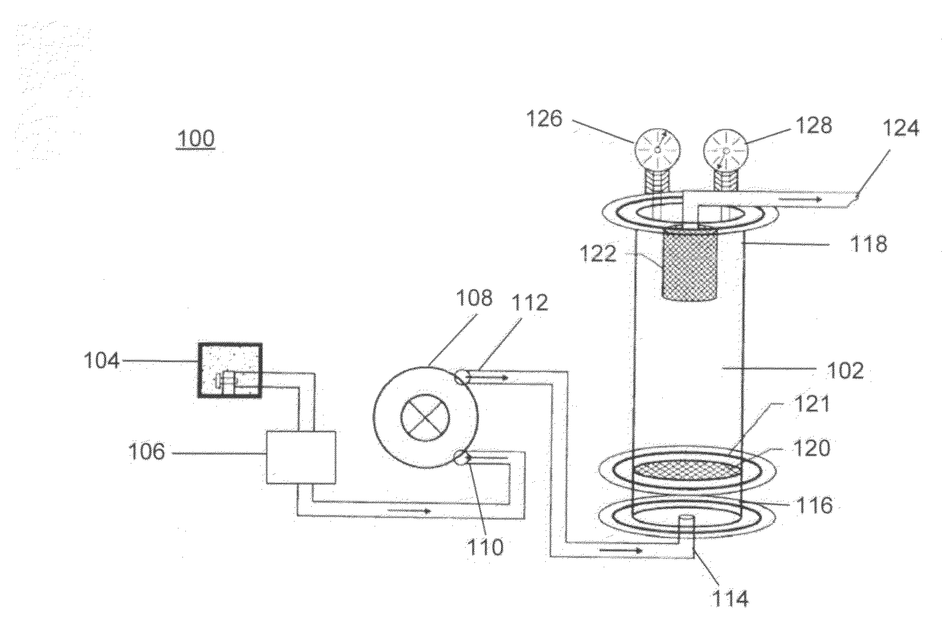
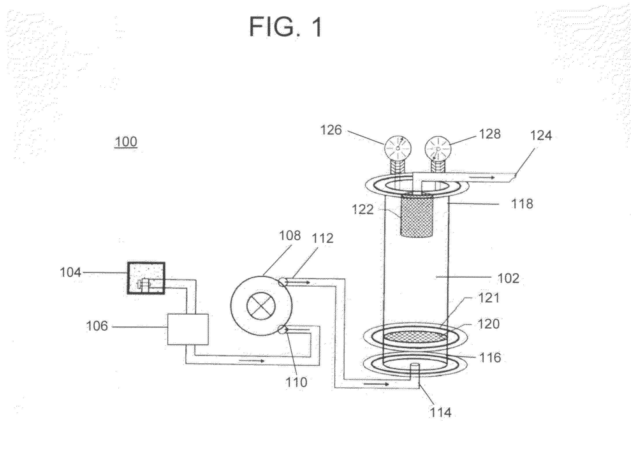
[0080]In Experiment 1, CO2 and SO2 were simultaneously sequestered from the flue gas of the coal fired plant. A fluidized bed reactor as described in the Example section was used. About 23 kg of fly ash having the chemical properties as described in Table 4 was loaded in the reactor. The reactor was run for about 2 hours and samples of fly ash were taken at 2, 8, 15, 30, 45, 60, 75, and 120 minutes. The chemical properties of the flue gas are also described in Table 4.

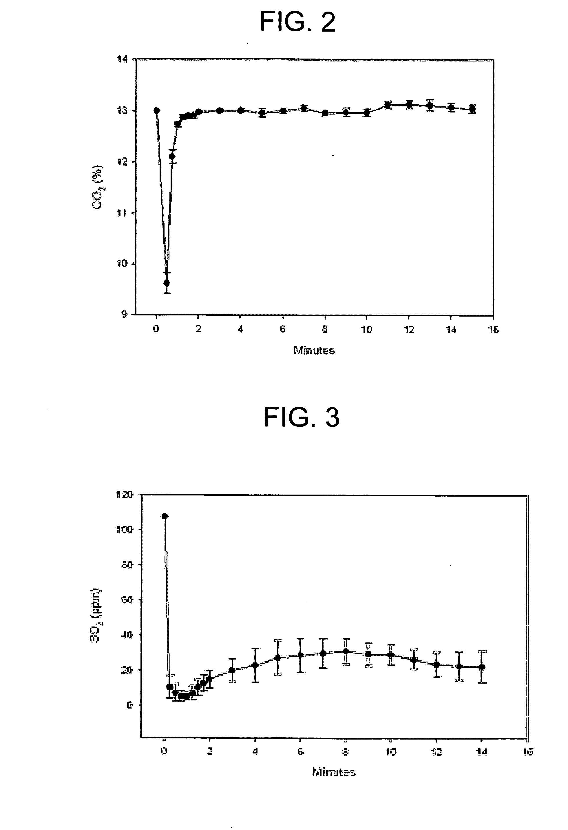
[0081]FIG. 2 is a graphical representation of carbon dioxide sequestering via Experiment 1. Referring to FIG. 2, the y-axis is the percentage concentration of carbon dioxide gas and the x-axis is the reaction time in minutes. As shown in FIG. 2, the average CO2 concentration decreased from about 13.0% to about 9.6% by reacting with the fly ash during the first minutes of the reaction.

[0082]FIG. 3 is a graphical representation of sulfur dioxide sequestrating via Experiment 1. Referring to FIG. 3, the y-axis represents c...

experiment 2

[0086]In this Experiment 2, CO2 and SO2 were simultaneously sequestered from the flue gas of the coal fired plant. A fluidized bed reactor as described in Experiment 1 was used. About 23 kg of fly ash having the chemical properties as described in Table 4 was loaded in the reactor, the reaction was run for 2 hours. A sample of reacted fly ash was taken at about 2 minutes. The chemical properties of the flue gas and fly ash are described in Table 4.

[0087]FIG. 5A is a SEM photomicrograph of fly ash prior to reaction in Experiment 2. FIG. 5B is an EDS spectra of fly ash prior to reaction in Experiment 2. Referring to FIGS. 5A and 5B, a fly ash sample was taken at location 502 and an EDS spectra was run on the sample. Table 5 below illustrates a mass percent of the control sample shown in FIGS. 5A and 5B.

TABLE 5Composition of Fly Ash (Control Sample)OFe[massNaAlSiKCa[mass%][mass %][mass %][mass %][mass %][mass %]%]59.084.4314.5016.71.560.862.8

[0088]FIG. 5C is a SEM photomicrograph of fl...


PUM

PropertyMeasurementUnit
Temperatureaaaaaaaaaa
Fractionaaaaaaaaaa

Abstract

The invention relates to an apparatus and method for reducing contaminants from industrial processes. More particularly, the invention is directed to a method of sequestering pollutants from flue gases in operational plants. The method includes sequestering contaminants from a point source by reacting an alkaline material with a flue gas containing contaminants to be sequestered, wherein the reaction has a rapid mass transfer rate to sequester at least a portion of the contaminants.

Description

[0001]This application claims benefit to and is a continuation-in-part of U.S. patent application Ser. No. 12 / 215,638, filed on Jun. 27, 2008, pending, which is a continuation of PCT Application No. PCT / US2006 / 049411, filed on Dec. 28, 2006, which claims benefit to U.S. Provisional Patent Application No. 60 / 755,959, filed on Jan. 3, 2006, all of which are hereby incorporated by reference for all purposes as if fully set forth herein.BACKGROUND OF THE INVENTION[0002]1. Field of the Invention[0003]The invention relates to an apparatus and method for reducing contaminants from industrial processes. More particularly, the invention is directed to a method of sequestering pollutants from flue gases in operational plants.[0004]2. Discussion of the Related Art[0005]There are a number of related art methods and apparatuses for reducing contaminants from industrial processes. For example, some potential processes for minimizing or capturing flue gas CO2 emissions include an integrated gasifi...

Claims


Application Information

Patent Timeline
IPC IPC(8): B01D53/62B01D53/56B01D53/50
CPCB01D53/40Y02C10/04B01D53/62B01D53/64B01D2251/30B01D2251/304B01D2251/306B01D2251/40B01D2251/402B01D2251/602B01D2257/302B01D2257/404B01D2257/504B01D2257/602F27B15/02F27B15/10F27B15/18B01D53/508Y02C20/40
Inventor REDDY, KATTA J.ARGYLE, MORRIS D.
Owner UNIVERSITY OF WYOMING
Why Eureka
Try Eureka