

Method of forming a high transparent carbon film
a carbon polymer and high-transparent technology, applied in the field of carbon polymer film forming, can solve the problems of difficult to form a polymer having a density of more than 1.2 g/cm, less than 0.05 extinction coefficient, 633 nm, etc., and achieve excellent characteristics
- Summary
- Abstract
- Description
- Claims
- Application Information
AI Technical Summary
Benefits of technology
Problems solved by technology
Method used
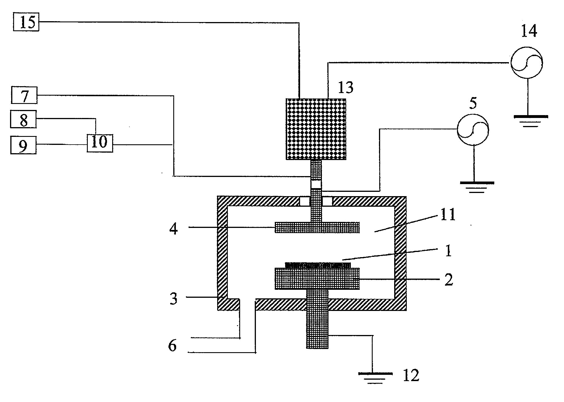
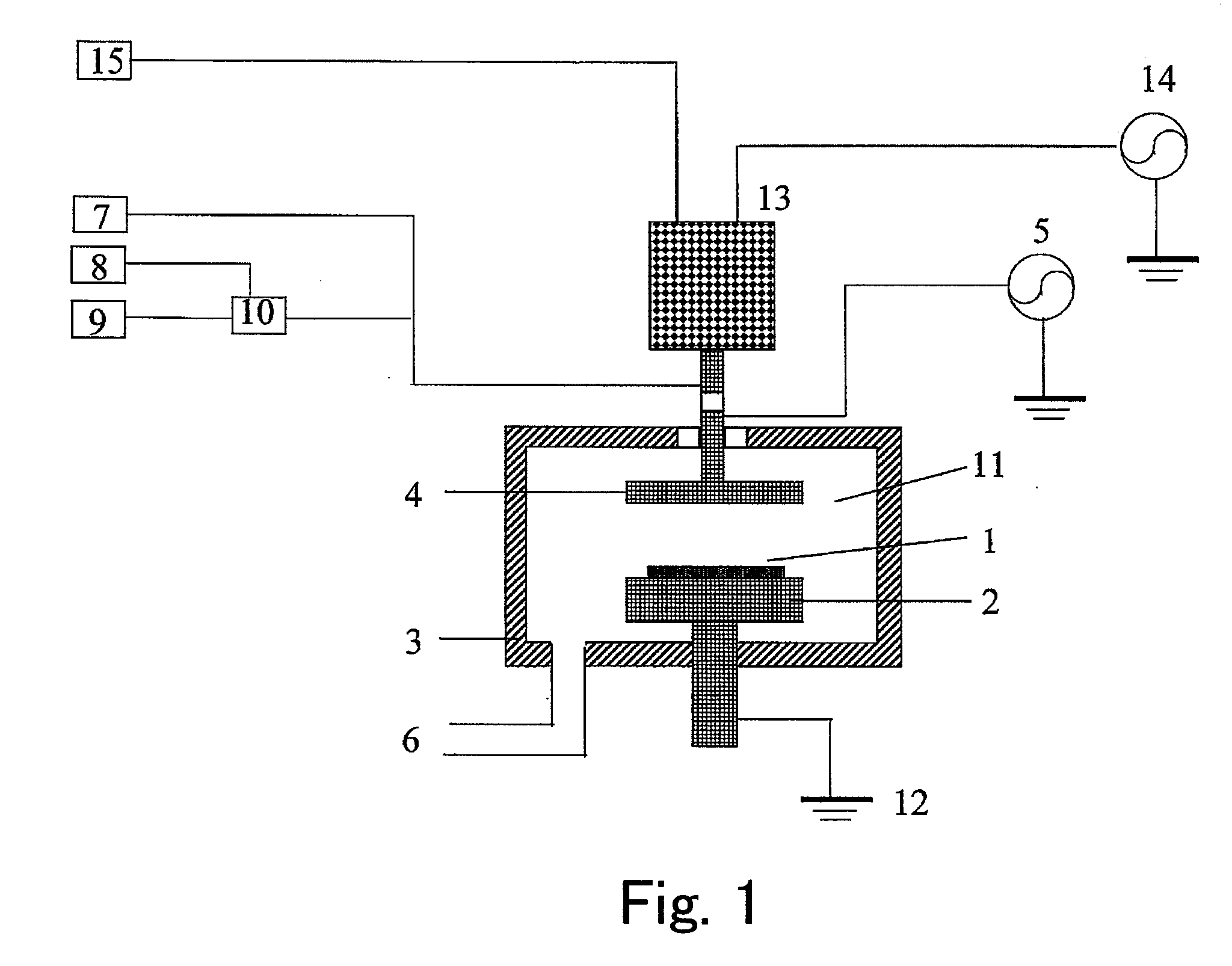
Image

Examples
example 1
[0079]Process conditions in this example and film formation results are shown as follows:
[0080]Process Conditions:
[0081]Precursor: Cyclopentane: 200 sccm
[0082]He supplied to vaporizer: 500 sccm
[0083]Temperature of vaporizer, vaporizer portion: 40° C.
[0084]Controlled temperature of gas inlet piping: 80° C.
[0085]Process gas He supplied to reactor: 500 sccm
[0086]RF Power 13.56 MHz: 2300 W
[0087]Pressure: 733 Pa
[0088]Susceptor temperature: 575° C.
[0089]Film formation time: 43 sec
[0090]Film Formation Results:
[0091]Thickness: 200 nm
[0092]RI(n)@633 nm: 1.87
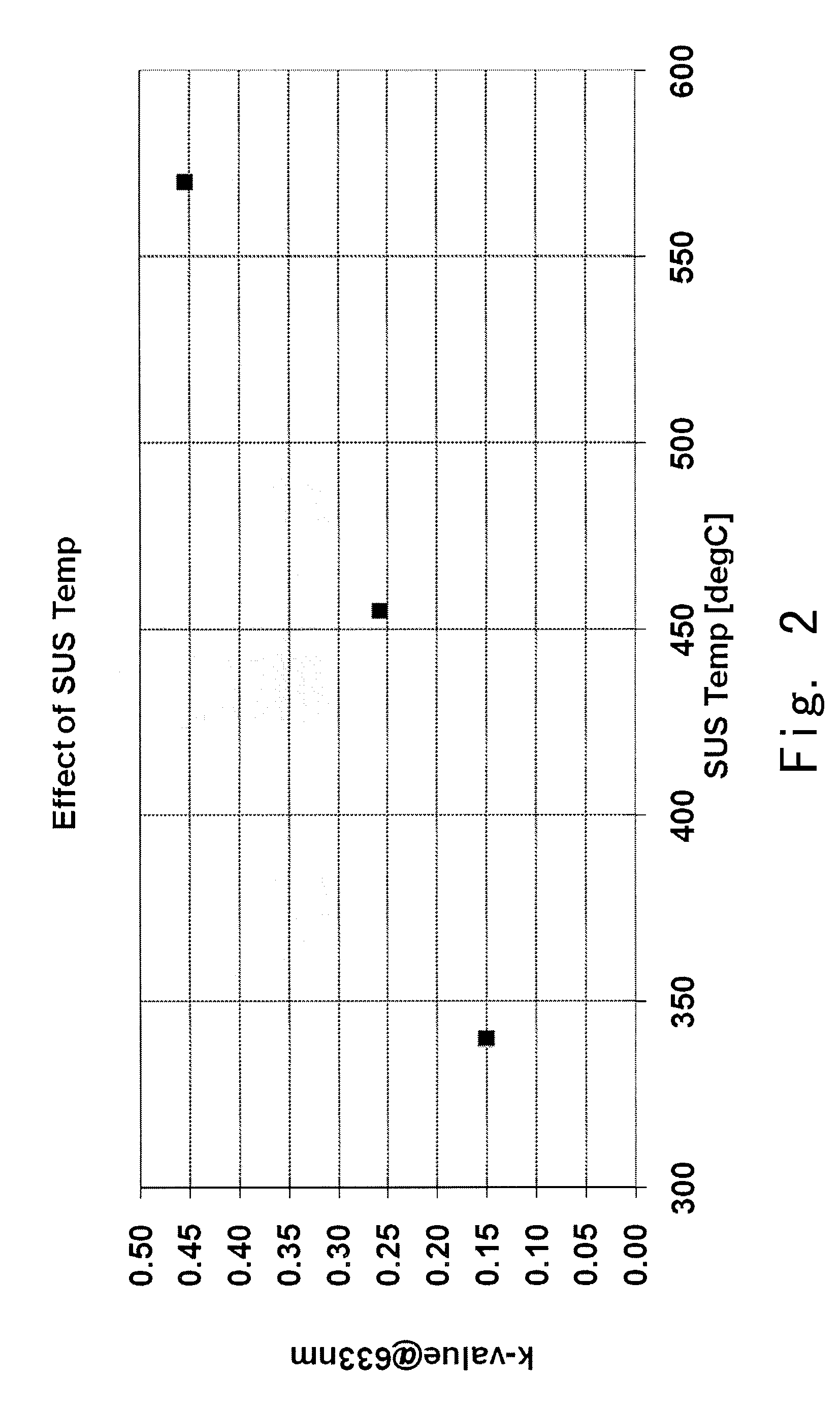
[0093]Extinction coefficient (k)@633 nm: 0.45 (see FIG. 2)
[0094]Density: 1.47 g / cm3
[0095]Modulus: 52 GPa
[0096]Hardness: 7.9 GPa
[0097]The film formed using cyclopentane (Example 1) shows fairly good physical properties. However, it has a poor optical performance.
example 2
[0098]Process conditions in this example were the same as in Example 1 except for the susceptor temperature set to 455° C. The deposition time was set according to the target thickness of 200 nm.
[0099]Film Formation Results:
[0100]Thickness: 200 nm
[0101]RI(n)@633 nm: 1.80
[0102]RI(k)@633 nm: 0.25 (see FIG. 2)
[0103]Density: 1.44 g / cm3
[0104]Modulus: 47 GPa
[0105]Hardness: 7.3 GPa
[0106]The film formed using cyclopentane (Example 2) shows fairly good physical properties. However, it has a poor optical performance although it is better than in Example 1.
example 3
[0107]Process conditions in this example were the same as in Example 1 except for the susceptor temperature set to 340° C. The deposition time was set according to the target thickness of 200 nm.
[0108]Film Formation Results:
[0109]Thickness: 200 nm
[0110]RI(n) @633 nm: 1.75
[0111]Extinction coefficient (k) @633 nm: 0.15 (see FIG. 2)
[0112]Density: 1.42 g / cm3
[0113]Modulus: 43 GPa
[0114]Hardness: 7.1 GPa
[0115]The film formed using cyclopentane (Example 3) shows fairly good physical properties. Also, it has a reasonable optical performance which is better than in Examples 1 and 2.
PUM
| Property | Measurement | Unit |
|---|---|---|
| boiling point | aaaaa | aaaaa |
| processing temperature | aaaaa | aaaaa |
| refractive index | aaaaa | aaaaa |
Abstract
Description
Claims
Application Information