
Photosensitive hardmask for microlithography

a microlithography and hardmask technology, applied in the field of photosens, can solve the problems of reducing the thickness of the photoresist, unable to offer sufficient etch resistance, and the current-available photoresist still etchs relatively quickly, so as to shorten the process time, less time, and less cost

Active Publication Date: 2009-12-03
BREWER SCI
View PDF0 Cites 52 Cited by
  • Summary
  • Abstract
  • Description
  • Claims
  • Application Information

AI Technical Summary

Benefits of technology

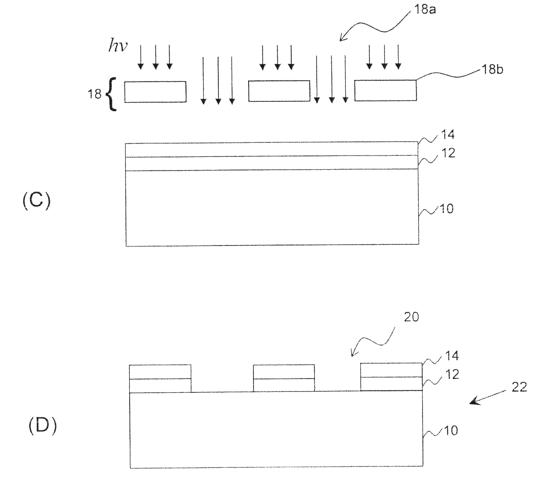
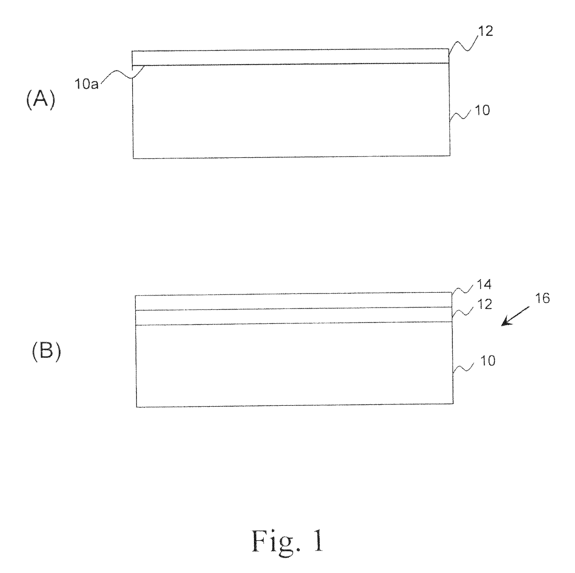
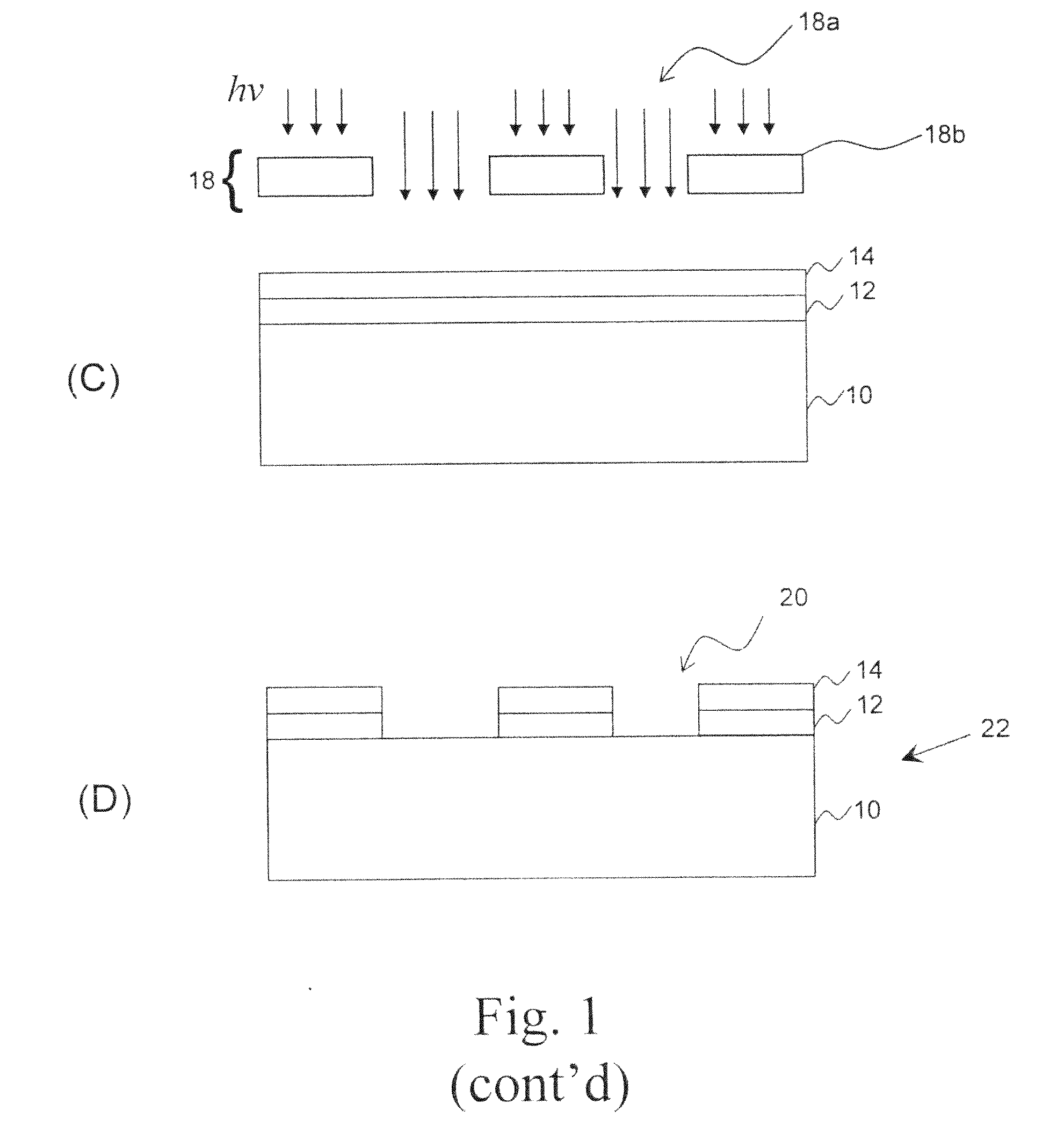
The present invention provides a new composition for making microelectronic structures that can decrease the required thickness of photoresist and shorten the process time by eliminating an etching step. This composition can be applied by spin-coating, which is faster and less expensive than traditional methods. Additionally, this invention enables the continuous CD shrinking to the 32-nm node and beyond, especially when coupled with a multiple patterning process, while also reducing the cost of ownership of current multilayer fabrication by eliminating an etch step. The invention also provides a method of making a microelectronic structure using this new composition. The resulting structure comprises a substrate with a hardmask layer that is contacted with a developer to remove the exposed portion of the hardmask layer.

Problems solved by technology

However, Rayleigh's law also shows that enhancing resolution causes the DOF to decrease.
However, the reduced photoresist thickness cannot offer sufficient etch resistance to transfer the pattern into the substrate, especially for 193-nm ArF photolithography.
Due to the transparency requirement, aromatic structures cannot be put into ArF resists, so most ArF resists etch even faster than previous photoresists.
Unfortunately, almost all currently-available photoresists still etch relatively rapidly under common hardmask plasma etch chemistries.
However, undercutting is very difficult to control in an isotropically developable bottom anti-reflective coating.
On the other hand, if they are coated on top of a spin-on carbon (SOC) planarization layer, those organic bottom anti-reflective coating materials are not effective as hardmasks.
However, the current litho-etch-litho-etch (LELE) process is very expensive, even in comparison to EUV lithography.
Thus, many existing processes still require a dry-etch step to transfer the patterns to the underlying layer.
The dry-etch step complicates the process and increases the cost and time involved.

Method used


Image

  • Photosensitive hardmask for microlithography
  • Photosensitive hardmask for microlithography
  • Photosensitive hardmask for microlithography

Examples


example 1

Hardmask Formulation I

[0050]In this procedure, a photosensitive hardmask was formulated by first diluting 3.5 grams of isopropanol solution of colloidal silica (˜30 wt % SiO2, average particle size 10-15 nm) (Organosilicasol™ IPA-ST; obtained from Nissan Chemical, Houston, Tex.) with 5 ml of PGME (obtained from Harcros Chemicals, St. Louis, Mo.). Then, 350 mg of trifunctional vinyl ether crosslinker (see Example 8) were added into the solution, together with 5 mg of pyridinium p-toluenesulfonate (PPTS; obtained from Aldrich, Milwaukee, Wis.). The mixture was stirred overnight at room temperature in a glass vial and then diluted further with PGME to a total solution weight of 56 grams. Next, 20 mg of triethanolamine (TEA; obtained from Aldrich, Milwaukee, Wis.) and 26 mg of the PAG di-(p-t-butylphenyl) iodonium tris(perfluoromethanesulfonyl)methide (DTBPI-C1; obtained from DAYCHEM Laboratories, Inc., Vandalia, Ohio) were added. This final formulation was filtered through a particle f...

example 2

Hardmask Formulation 2 and Photosensitivity Test

[0053]In this procedure, a second hardmask formulation was prepared by adding 10 mg of DTBPI-C1 PAG to 10 mg of hardmask Formulation 1 from Example 1 above to produce a more photosensitive Formulation 2. The formulation was spin-coated at 2,000 rpm onto a silicon substrate and then baked at 130° C. for 60 seconds. The film was then exposed to UV light through a 248-nm filter for various periods of time (i.e., 5, 8, 10, and 12 seconds). After PEB at 130° C. for 60 seconds and development using PD523AD, the remaining thickness (in nanometers) of the exposed areas was measured and plotted against the exposure dose (in mJ / cm2). The representative contrast curve shown in FIG. 2 clearly indicates the sharp contrast of developer solubility before and after the exposure dose reached 25 mJ / cm2.

example 3

Imaging Using Formulation 2 on Anti-Reflective Coating Material

[0054]In this procedure, a structure was prepared and patterned using hardmask Formulation 2 from Example 2 above. First, an anti-reflective coating material (ARC® 29A; obtained from Brewer Science, Inc., Rolla, Mo.) was spin-coated onto a silicon wafer at 2,500 rpm, followed by baking at 205° C. The anti-reflective coating had a thickness of 80 nm. Formulation 2 was spin-coated at 2,000 rpm on top of the ARC® 29A coating and then baked at 130° C. for 60 seconds. The film stack was exposed to UV light through a 248-nm filter to give an exposure of >25 mJ / cm2 (according to the contrast curve in FIG. 2). After PEB at 130° C. for 60 seconds and development using PD523AD, the resulting patterns were imaged under optical microscopy to give FIG. 3, which shows positive micropatterns (down to 10-μm lines) that were resolved using hardmask Formulation 2.


PUM

PropertyMeasurementUnit
particle sizeaaaaaaaaaa
sizesaaaaaaaaaa
solubilityaaaaaaaaaa

Abstract

New hardmask compositions comprising non-polymeric, metal-containing nanoparticles dispersed or dissolved in a solvent system and methods of using those compositions as hardmask layers in microelectronic structures are provided. The compositions are photosensitive and capable of being rendered developer soluble upon exposure to radiation. The inventive hardmask layer is patterned simultaneously with the photoresist layer and provides plasma etch resistance for subsequent pattern transfer.

Description

CROSS-REFERENCE TO RELATED APPLICATIONS[0001]This application claims the priority benefit of a provisional application entitled PHOTOSENSITIVE HARDMASK FOR MICROLITHOGRAPHY, Ser. No. 61 / 047,302, filed Apr. 23, 2008, incorporated by reference herein.BACKGROUND OF THE INVENTION[0002]1. Field of the Invention[0003]The present invention relates in general to compositions and microlithographic processes that allow use of extremely thin photoresist layers to form microelectronic structures.[0004]2. Description of the Prior Art[0005]The advances of microelectronic manufacture are reflected by the density and dimensions of semiconductor structures created by the microphotolithographic process. The demand for high density and small critical dimension (CD) has been constantly pushing photolithography technology to its limits. To keep pace with the semiconductor industry roadmap, next-generation patterning materials and innovative lithographic processes will be needed to work in unison for hig...

Claims


Application Information

Patent Timeline
Patent Type & Authority Applications(United States)
IPC IPC(8): B32B3/10B32B5/16G03F7/20G03F7/004
CPCG03F7/039G03F7/091G03F7/094G03F7/11Y10T428/24612Y10S430/128Y10S430/114Y10T428/24851Y10T428/24893Y10S430/151H01L21/0273H01L21/0337
Inventor XU, HAOMERCADO, RAMIL-MARCELO L.GUERRERO, DOUGLAS J.
Owner BREWER SCI
Learn More