Cardiac ablation catheters for forming overlapping lesions

a catheter and atria technology, applied in the field of ablation instruments, can solve the problems of ineffective quivering, inability to achieve asymmetric atria, and inability to efficiently atria, and achieve the effect of avoiding atria resection, avoiding resection, and avoiding resection

Inactive Publication Date: 2009-12-03
CARDIOFOCUS INC
View PDF99 Cites 77 Cited by
  • Summary
  • Abstract
  • Description
  • Claims
  • Application Information

AI Technical Summary

Benefits of technology

[0021]In a further aspect of the invention, the percutaneous catheters of the present invention can also include a reflection sensor, such as an endoscope positionable in the instrument's distal end region to obtain an image. The image allows the clinician to visualize the anatomy of the vein, the location of side branches and the position of the instrument relative to the vein. The clinician can determine whether contact has been achieved (or blood has been cleared from an ablative energy transmission path) and the optimum location for ablation or radiation dosing before ablation begins or while ablation is occurring.
[0022]In one embodiment, percutaneous ablation catheters are disclosed having at least one central lumen and one or more compliant balloon structures at the distal end region of the instrument. Also disposed in the distal end region is an illuminating light source and an endoscope capable of collecting sufficient light to relay an image to the user. The instruments can further include one or more energy emitting elements, which are preferably independently positionable within the lumen of the instrument (e.g., along a longitudinal axis of the balloon) and adapted to project ablative energy through a transmissive region of the instrument body (and / or balloon) to a target tissue site. The energy can be delivered without the need for contact between the energy emitter and the target tissue so long as a clear transmission pathway (e.g., through the fluid of the inflated balloon) is established. The endoscope element of the instrument allows the clinician to see if such a pathway is clear.
[0023]Moreover, when the position of the radiant energy emitter can be varied, endoscopic guidance permits the clinician to select a desired location and dose for the lesion. Endoscopic inspection thus permits the clinician to define a priori an “ablation plan” before creating an overlapping series of spot lesions. Based on the locations and sizes of the lesions, the present inventions permits the user to select a suitable energy level, e.g., to compensate for the power changes due to the size of the lesion and / or to compensate for the amount of attenuation caused by projecting energy to a target site across a greater distance.

Problems solved by technology

The regular pumping function of the atria is replaced by a disorganized, ineffective quivering as a result of chaotic conduction of electrical signals through the upper chambers of the heart.
Devices that rely upon resistive or conductive heat transfer can be prone to serious post-operative complications.
To achieve this, the temperature at the contact surface will typically be raised to greater than 100° C. In this temperature regime, there is a substantial risk of tissue destruction (e.g., due to water vaporization micro-explosions or due to carbonization).
Charring of the surface of the heart tissue, in particular, can lead to the creation of blood clots on the surface and post-operative complications, including stroke.
Cardiac ablation instruments also suffer from a variety of design limitations.
For example, the shape of the heart muscle adds to the difficulty in accessing cardiac structures, such as the pulmonary veins on the anterior surface of the heart.
Moreover, because the lesion is formed by an ablation element carried on the surface of the balloon element, the balloon shape inherently limits the locations where a lesion can be formed, i.e., the lesion must be formed at least partially within the pulmonary vein.
With the Swartz et al. device, like the Lesh device, the region where tissue ablation can occur is limited by the design.
Ablation within the pulmonary vein can result in complications.
Overtreatment deep within a vein can result in stenosis (closure of the vein itself), necrosis or other structural damage, any of which can necessitate immediate open chest surgery.
A limitation of these commonly utilized instruments is the lack of site selectability.
Practically speaking, each such percutaneous instrument is inherently limited by its design to forming an ablative lesion at one and only one location.
It is not possible to form the lesion at another location because the heating element must contact the target tissue.
Another limitation of such known instruments and methods is their inability to accommodate the varied geometry of the heart.
Thus, when the above-described expandable, contact heating devices encounter an irregularly-shaped ostia, the result can be an incompletely formed (non-circumferential) lesion.
Moreover, the size or shape of the pulmonary vein ostia that are encountered may be too big or too small for the selected balloon catheter and it may be necessary to remove the first balloon catheter from the patient and replace it with another instrument having a balloon element of a different size.
Replacement of the catheter with another before a procedure can begin (or in the middle of a multiple vein ablation protocol) can substantially increase the overall duration of the procedure and / or increase the chance of trauma.

Method used


Image

  • Cardiac ablation catheters for forming overlapping lesions
  • Cardiac ablation catheters for forming overlapping lesions
  • Cardiac ablation catheters for forming overlapping lesions

Examples


Embodiment Construction

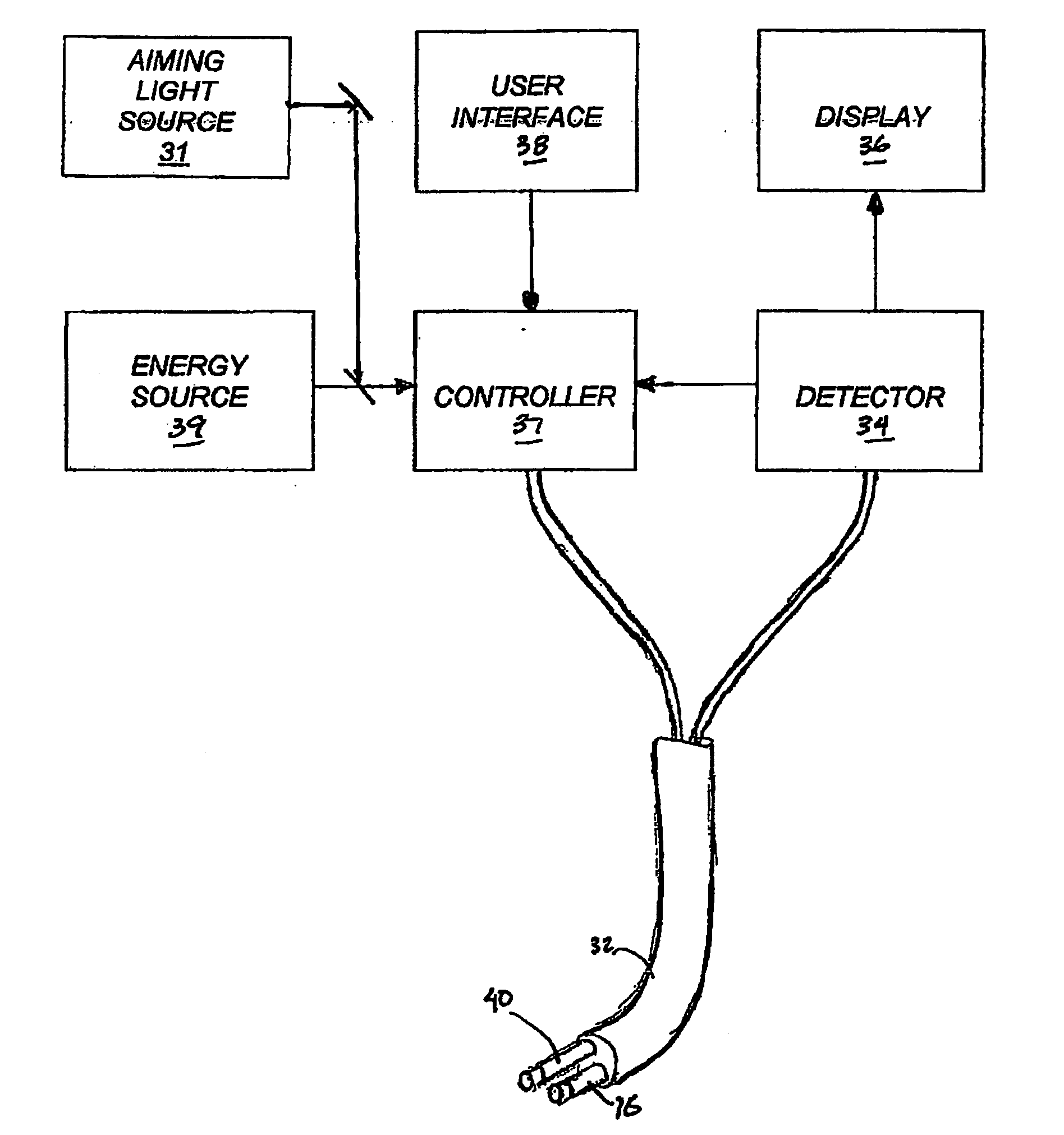
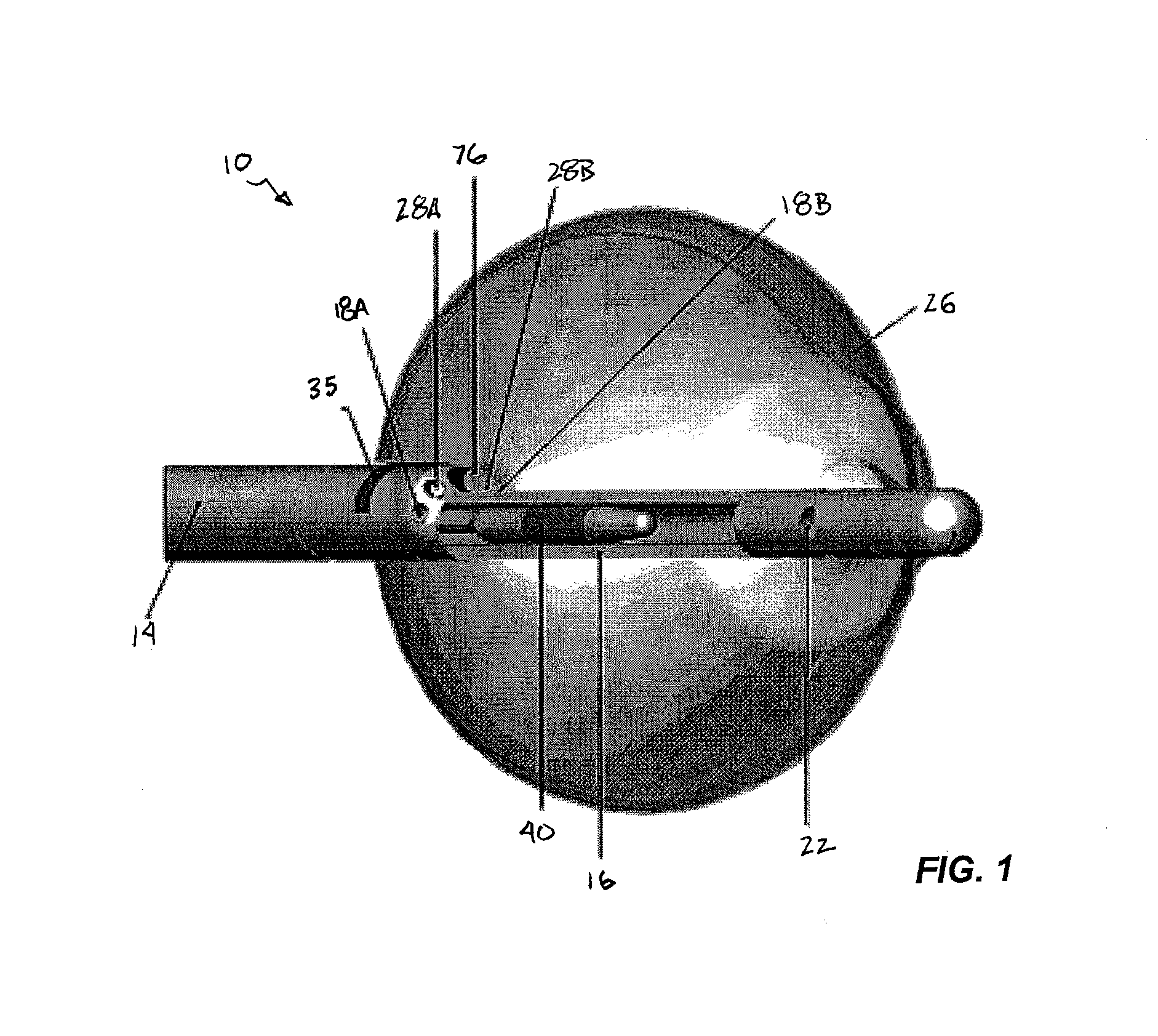
[0060]FIG. 1 provides a schematic, cross-sectional view of an ablation instrument 10 according to the invention, including an elongate body 14, a central lumen tubing 16 and a compliant balloon 26 inflatable via one or more ports 22 in the central tubing. The central tubing 16 can also house an energy emitter that is capable of both axial movement and rotation within the tubing 12. Within the elongated body (also referred to herein as the catheter body) there can be a plurality of additional lumens, through which certain devices or instruments can been passed. For example, as shown in FIG. 1, the catheter body 14 also provides lumens 18A and 18B for extraction (or circulation) of a inflation fluid, an endoscope 76 and illuminations fibers 28A and 28B. The catheter body can carry a marker to assist the clinician in proper placement of the device, e.g., a radiopaque marker to aid in fluoroscopic detection.

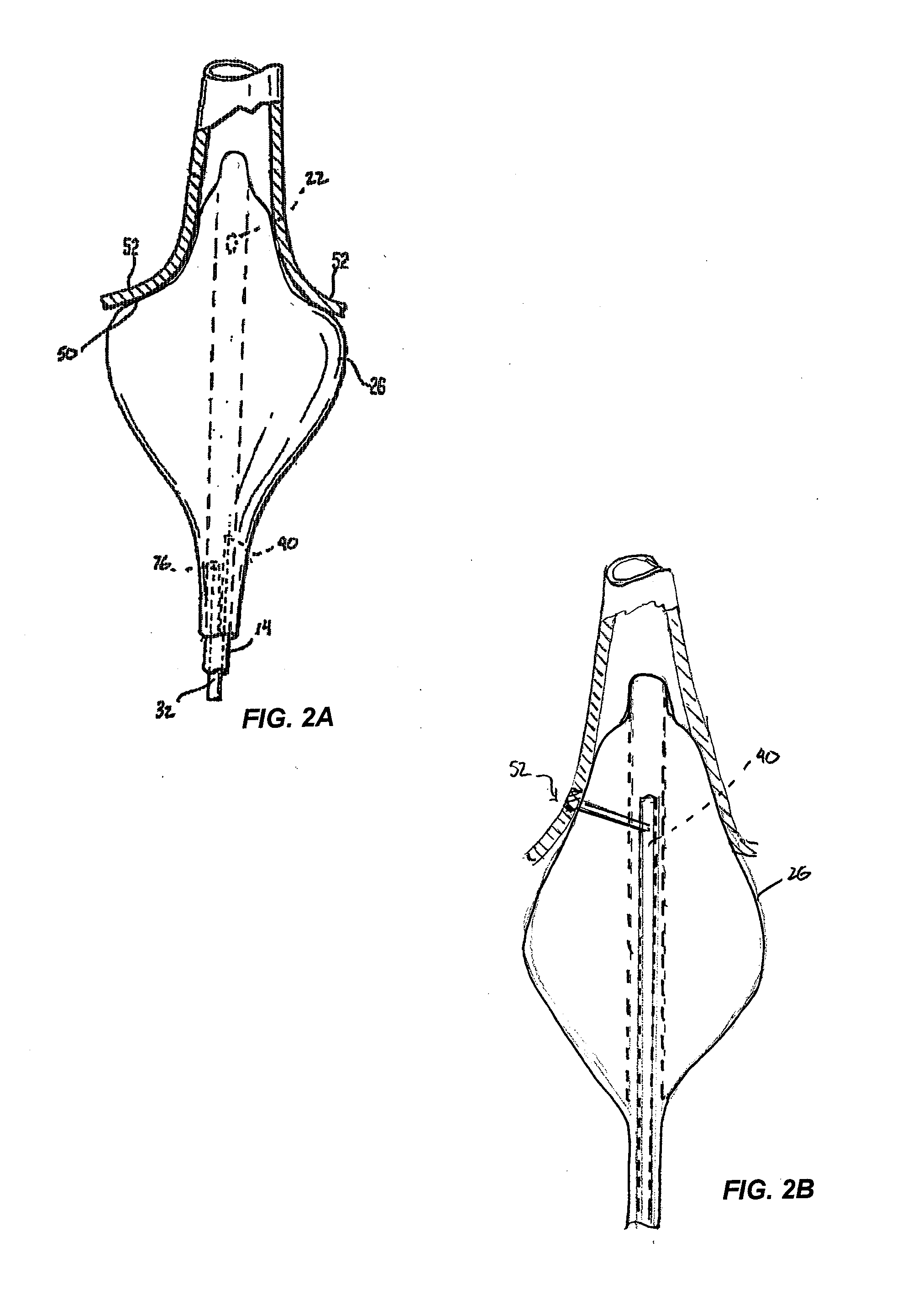
[0061]As shown in FIG. 2A, the instrument is preferably designed such that upon ...


PUM


Abstract

Methods and instruments are disclosed for creating lesions in tissue, especially cardiac tissue, for treatment of arrhythmias and the like, by employing an elastic balloon and an energy emitter, which is independently positionable within the lumen of the instrument and adapted to project a series of spots of ablative energy through a transmissive region of the balloon to a target tissue site. The energy emitter preferably is configured such the spots of energy result in a series of lesions formed in the target tissue region when the emitter is activated, the lesions having an average area ranging from about 5 mm2 to about 100 mm2. In one aspect of the invention, percutaneous ablation instruments are disclosed in the form of catheter bodies having one or more balloon structures at the distal end region of the instrument and an energy emitting element, which is independently positionable and rotatable within a lumen of the instrument and adapted to project ablative energy through a transmissive region of the balloon to a target tissue site in contact with, or proximal to, the balloon surface.

Description

REFERENCE TO RELATED APPLICATIONS[0001]This application is a continuation-in-part of U.S. patent application Ser. No. 10 / 357,156, filed on Feb. 3, 2003 and currently pending, which is a continuation-in-part of U.S. patent application Ser. No. 09 / 924,394, filed on Aug. 7, 2001, now U.S. Pat. No. 6,579,285 issued Jun. 17, 2003. Additionally, U.S. patent application Ser. No. 10 / 357,156 is a continuation-in-part of U.S. patent application Ser. No. 09 / 616,275, filed on Jul. 14, 2000, now U.S. Pat. No. 6,626,900 issued Sep. 30, 2003, which is a continuation-in-part of U.S. patent application Ser. No. 09 / 602,420 filed on Jun. 23, 2000, now U.S. Pat. No. 6,572,609 issued Jun. 3, 2003, which is a continuation-in-part of U.S. patent application Ser. No. 09 / 357,355, filed on Jul. 14, 1999, now U.S. Pat. No. 6,423,055 issued Jul. 23, 2002. The teachings of all of these prior related applications are hereby expressly incorporated by reference.BACKGROUND OF THE INVENTION[0002]The present disclosu...

Claims


Application Information

Patent Timeline
Patent Type & Authority Applications(United States)
IPC IPC(8): A61B18/24
CPCA61B2018/2261A61B2017/00057A61B2018/0097A61B2019/465A61B2018/2266A61B18/245A61B2017/00061A61B2018/2272A61N7/02A61B2090/065
Inventor MELSKY, GERALDSAGON, STEPHEN W.STANCAMPIANO, ALFREDARNOLD, JEFFREY M.BAXTER, LINCOLN S.
Owner CARDIOFOCUS INC
Why Eureka
Try Eureka