Lithium cell with cathode containing iron disulfide

Inactive Publication Date: 2009-12-24
THE GILLETTE CO
View PDF27 Cites 19 Cited by
  • Summary
  • Abstract
  • Description
  • Claims
  • Application Information

AI Technical Summary

Benefits of technology

[0027]The electrolyte mixture of the invention provides the electrochemical properties needed to allow efficient electrochemical discharge of the Li/FeS2 cell. In particular the electrolyte mixture of the invention provides the electrochemical properties needed to allow even high rate pulsed discharge demands of high power electronic devices such as digital cameras. Thus, an Li/FeS2 cell can be produced using the electrolyte mixture of the invention resulting as a suitable primary cell for use in a digital camera normally powered by rechargeable cell. Aside from exhibiting very good electrochemical properties which allows efficient discharge of the Li/FeS2 cell, the electrolyte solvent mixture of the invention has the advantage of having relatively low viscosity.
[0028]Applicants herein have determined that in a Li/FeS2 cell it is advantageous to have an electrolyte of low viscosity, between about 0.9 and 1.4 centipoise. The electrolyte of the invention comprising lithium iodide salt dissolved in a solvent mixture comprising 1,3-dioxolane (DX) and 1,3-dimethy-2-imidazolidinone (DID) has low viscosity between about 0.9 and 1.4 centipoise, typically between about 1.2 and 1.4 centipoise. Such low viscosity level helps to improve Li/FeS2 cell performance, because it promotes good lithium ion (Li+) transport between anode and cathode.
[0029]In order for the Li/FeS2 cell to discharge properly lithium ions from the anode must have enough ionic mobility enabling good transport across the separator and into the FeS2 cathode. At the cathode the lithium ions participate in the reduction reaction of sulfur ions producing LiS2 at the cathode. Electrolytes of low viscosity are highly desirable for the Li/FeS2 cell because 1) that it reduces lithium ion (L

Problems solved by technology

This is because undesirable oxidation/reduction reactions between the electrolyte and electrode materials (either discharged or undischarged) could thereby gradually contaminate the electrolyte and reduce its effectiveness or result in excessive gassing.
This in turn can result in a catastrophic cell failure.
The choice of a particular organic solvent or mixture of different organic solvents for use in conjunction with any one or more lithium salts to produce a suitable electrolyte for the Li/FeS2 cell is challenging.
But r

Method used


Image

  • Lithium cell with cathode containing iron disulfide
  • Lithium cell with cathode containing iron disulfide
  • Lithium cell with cathode containing iron disulfide

Examples


example

Comparative and Experimental Test Lithium Coin Cells with Cathode Comprising FeS2

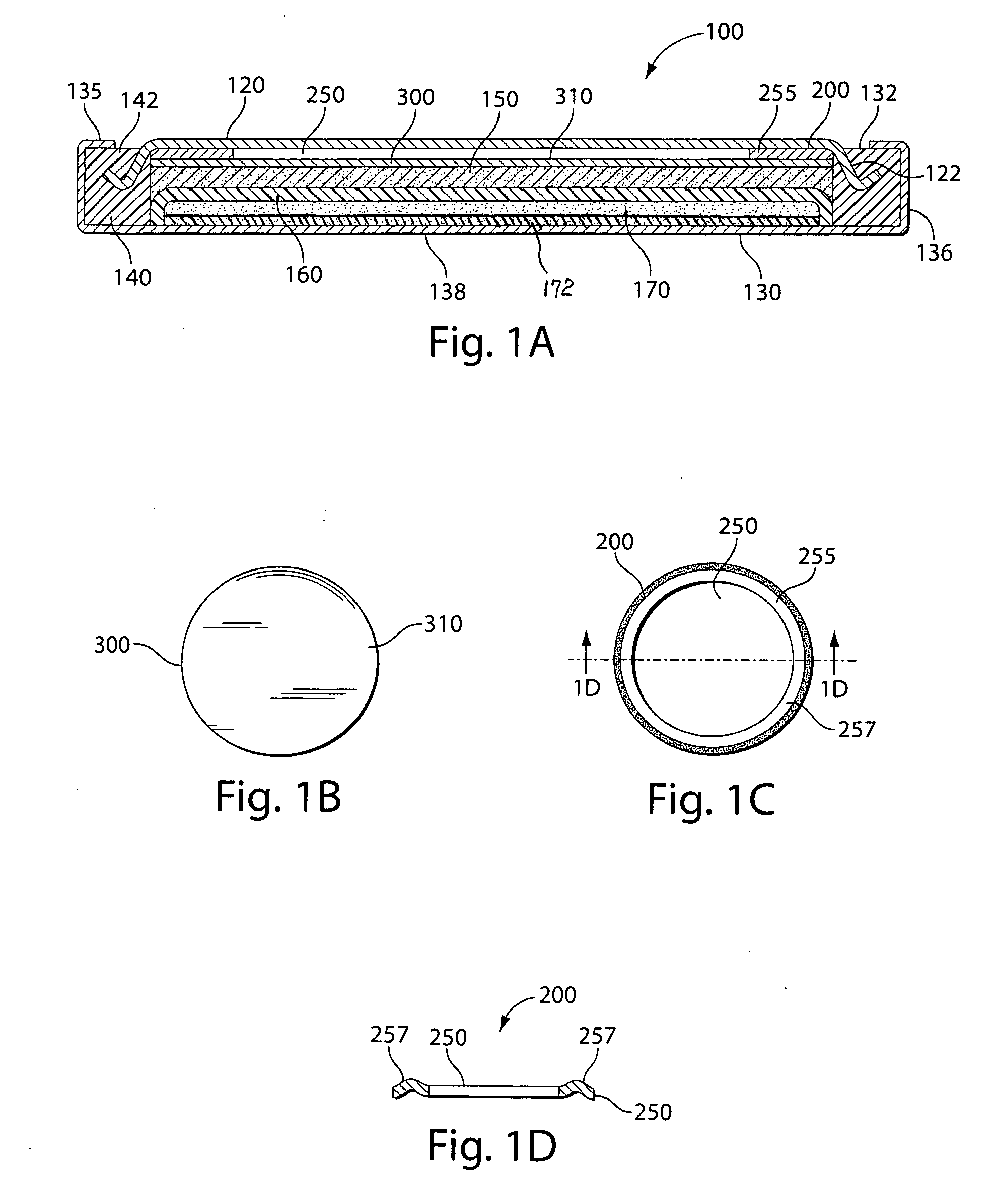
[0075]The Comparative and Experimental Test Li / FeS2 coin cells 100 (FIG. 1A) were prepared as follows:

Comparative and Experimental Test Coin Cell Assembly:

[0076]A coin shaped cathode housing 130 of aluminum plated steel and a coin shaped anode housing 120 of nickel plated steel is formed of a similar configuration shown in FIG. 1A. The finished cell 100 had an overall diameter of about 20 mm and a thickness of about 3 mm. (This is the size of a conventional ASTM size 2032 coin cell.) The weight of FeS2 in the cathode housing 130 was 0.0232 g. The lithium in the anode housing 120 was in electrochemical excess.

[0077]In forming each cell 100 a plastic insulating of ring shape 140 was first fitted around the side wall 122 of anode housing 120 (FIG. 1A). A spring ring 200 of stainless steel was placed against the inside surface of the anode housing 120. Ring 200 is inserted into anode housing 120 without t...


PUM


Abstract

A primary cell having an anode comprising lithium and a cathode comprising iron disulfide (FeS2) and carbon particles. The electrolyte comprises a lithium salt dissolved in a solvent mixture which contains 1,3-dioxolane and preferably 1,3-dimethyl-2-imidazolidinone. A cathode slurry is prepared comprising iron disulfide powder, carbon, binder, and a liquid solvent. The mixture is coated onto a conductive substrate and solvent evaporated leaving a dry cathode coating on the substrate. The anode and cathode can be spirally wound with separator therebetween and inserted into the cell casing with electrolyte then added.

Description

FIELD OF THE INVENTION[0001]The invention relates to lithium cells having an anode comprising lithium and a cathode comprising iron disulfide and an electrolyte comprising a lithium salt, preferably lithium iodide and solvent which includes 1,3-dioxolane and 1,3-dimethyl-2-imidazolidinone.BACKGROUND[0002]Primary (non-rechargeable) electrochemical cells having an anode of lithium are known and are in widespread commercial use. The anode is comprised essentially of lithium metal. Such cells typically have a cathode comprising manganese dioxide, and electrolyte comprising a lithium salt such as lithium trifluoromethane sulfonate (LiCF3SO3) dissolved in an organic solvent. The cells are referenced in the art as primary lithium cells (primary Li / MnO2 cells) and are generally not intended to be rechargeable. Alternative, primary lithium cells with lithium metal anodes but having different cathodes, are also known. Such cells, for example, have cathodes comprising iron disulfide (FeS2) and...

Claims


Application Information

Patent Timeline
IPC IPC(8): H01M6/16H01M4/58
CPCH01M4/06H01M4/134H01M4/136H01M4/382H01M4/405H01M4/5815Y02E60/122H01M4/661H01M6/164H01M2300/0017H01M2300/0037H01M2300/004H01M2300/0091H01M4/625Y02E60/10
Inventor JIANG, ZHIPINGFRIGUGLIETTI, LEIGHKOULOURIS, THOMAS N.
Owner THE GILLETTE CO
Why Eureka
Try Eureka