

Gas Purification by Adsorption of Hydrogen Sulfide
a technology of hydrogen sulfide and gas purification, which is applied in the direction of hydrogen separation using solid contact, separation process, products, etc., can solve the problems of significant differences between the performance of these and other adsorbents
- Summary
- Abstract
- Description
- Claims
- Application Information
AI Technical Summary
Benefits of technology
Problems solved by technology
Method used
Image

Examples
example 1
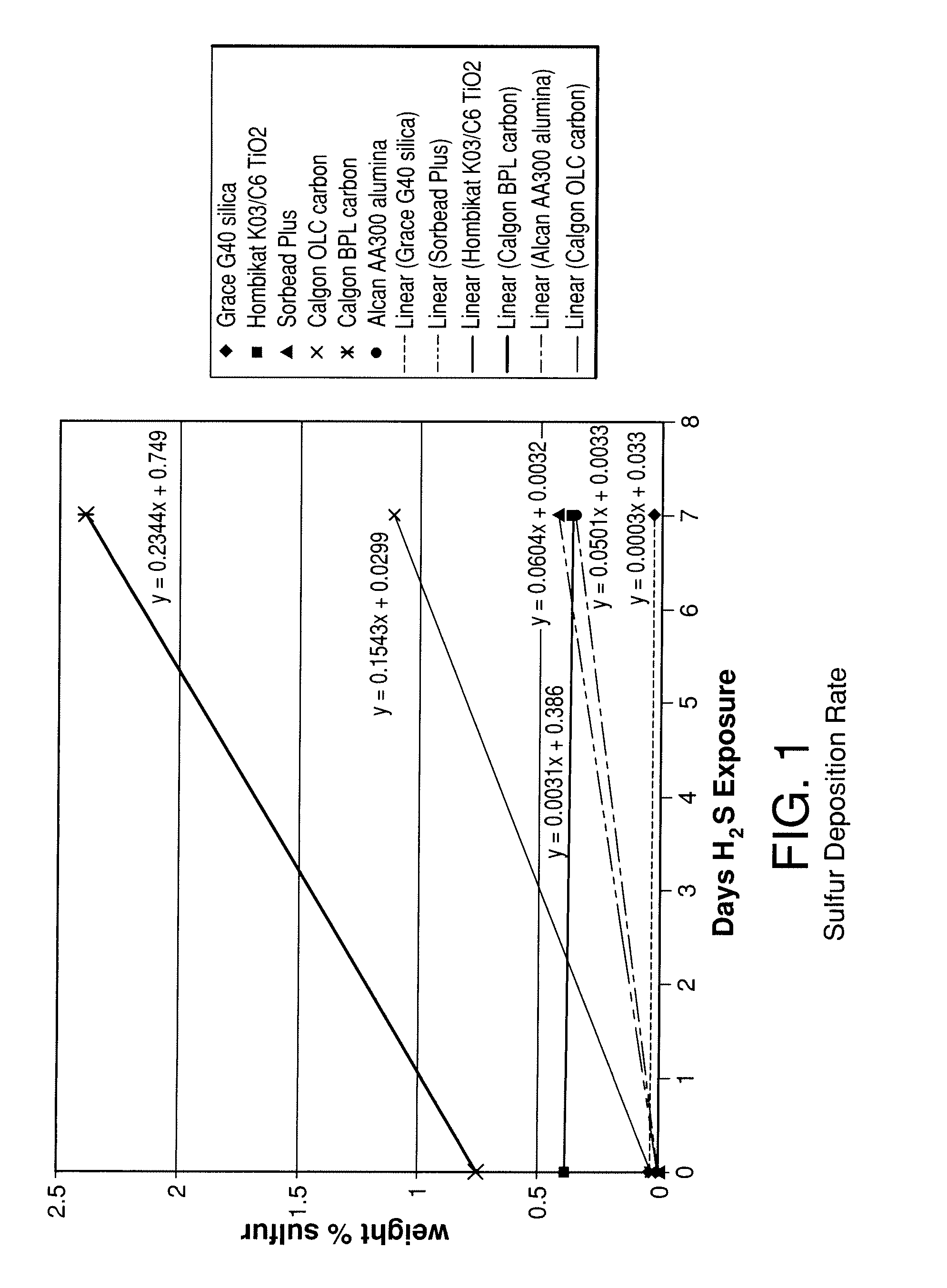
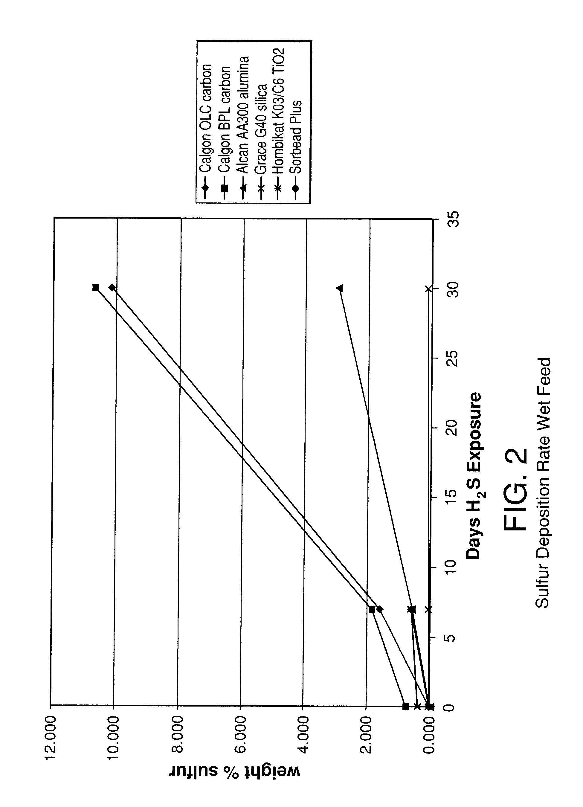
[0089]The stability of various adsorbents was tested upon exposure to H2S containing synthesis gas. The adsorbents tested included two activated carbons (Calgon 12×30 OLC, coconut-based and Calgon 4×10 BPL, coal-based), an activated alumina (Alcan 8×14 AA300), high purity silica gel (Grace Grade-40 99.7% SiO2), a low purity silica gel (Engelhard Sorbead Plus, 99.0% SiO2) a polymeric resin (Dowex Optipore V-493) and a titania (Hombikat K03 / C6). Packed beds were filled with 20-50 g of the above samples and exposed to approximately 350 cc / min gas flow at 400 psig (2760 kPa) and 20° C. The gas consisted of a flow of 1% H2S, 8% CO, 37% CO2, and balance H2. Seven additional beds were packed with the same adsorbents and were exposed to the same feed gas, although saturated with water at room temperature. The beds were held at ambient temperature during the experiments.
[0090]Adsorbent samples were removed from the beds at various time intervals to evaluate the adsorbents chemical compositio...
example 2
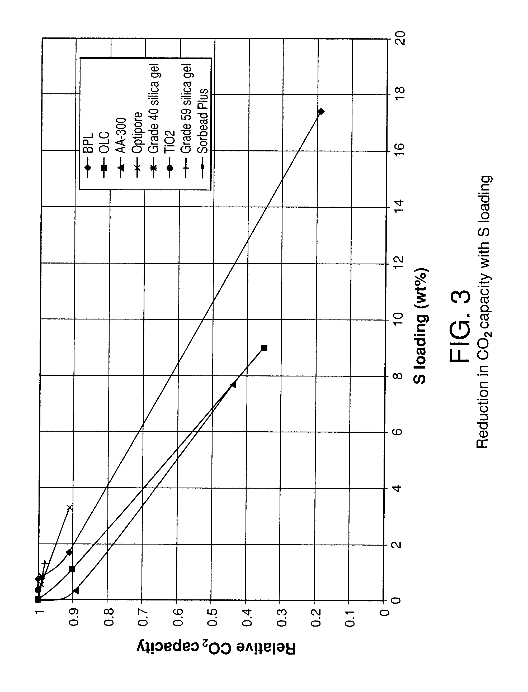
[0095]To better understand the effect of surface chemistry on the reaction of adsorbents with H2S, the zero point of charge (zpc) of the various adsorbents was tested. The zpc of a material is the pH at which the surface of the material carries no net electric charge. The zero point of charge for the various materials was determined by placing 20 grams of adsorbent in 100 ml of water and testing the pH after 24 hours. The pH of the initial solution was 7.2 and N2 was bubbled through the solution during the 24 hour hold period. Table 1 below shows various properties of the adsorbents tested including BET surface area, zpc, the sulfur deposition rate determined from FIG. 1 up to 7 days of exposure (slope of FIG. 1 from linear regression best fit) and the percentage loss in CO2 capacity as a function of sulfur loading derived from FIG. 3 (slope of FIG. 3 from linear regression up to seven days S accumulation). This value then corresponds to the percentage of CO2 capacity lost for each ...
example 3
[0097]Experiments were carried out to determine the effect of adsorption temperature on sulfur deposition as well as the effect of silica gel type on sulfur deposition. The experiments were carried out as those described in Example 1 with Grace Grade 40 silica gel and Engelhard Sorbead Plus silica gel at 20 and 60° C. feed temperatures. The results of that testing are shown in FIG. 5. The results clearly show that 1) the type of silica gel impacts the rate of sulfur deposition and 2) the higher the feed temperature, the higher the sulfur deposition rate. These data suggest that 1) low feed temperatures to the PSA are desired and 2) high purity silica gel (greater than 99%) is more robust than lower purity silica gel, having not only the lower loss of capacity with a given sulfur loading demonstrated in FIG. 3, but also a lower sulfur loading in a given period of use.
PUM
| Property | Measurement | Unit |
|---|---|---|
| Fraction | aaaaa | aaaaa |
| Time | aaaaa | aaaaa |
| Flow rate | aaaaa | aaaaa |
Abstract
Description
Claims
Application Information