Process and installation for generating electrical energy in a gas and steam turbine (combined cycle) power generating plant

a technology of gas and steam turbines and power generating plants, which is applied in the direction of electric generator control, machines/engines, mechanical equipment, etc., can solve the problems of lump coal being used, coal gas being used in the power generating plant of the combined cycle, and a series of byproducts, so as to achieve the effect of reducing the probability of pollution and increasing the carbon dioxide conten

Inactive Publication Date: 2010-02-11
SIEMENS VAI METALS TECHNOLOGIES GMBH & CO
View PDF15 Cites 45 Cited by
  • Summary
  • Abstract
  • Description
  • Claims
  • Application Information

AI Technical Summary

Benefits of technology

[0053]The present invention aims to avoid and overcome the aforementioned problems and disadvantages occurring in the prior art and has the object of providing a process for generating electrical energy in a gas and steam turbine (combined cycle) power generating plant which makes it possible to obtain energy with the smallest possible occurrence of pollutants and an increa...

Problems solved by technology

A further restriction for a combined cycle power generating plant operated with coal gas is also attributable to the currently restricted gasification performances of the gasification processes that are available on the market.
A disadvantage of this process is that it produces a series of byproducts, such as tars, slurries and inorganic compounds such as ammonia.
However, because of the fixed bed type of operation, only lump coal can be used.
As a result, the efficiency of the gasification is adversely influenced.
This means that pyrolysis gases and tars leave the gasifier with the raw gas and have to be removed in a downstream gas cleaning operation.
However, at 1 tonne of coal/hour, the power output is too small to be able to cover the gas demand of an IGCC installation.
The pressure is too low for IGCC power generating plants.
However, there are so far no large-scale commercial plants.
This process is also not yet commercially available in larger units.
However, at approximately 6-8 tonnes of coal (daf)/hour, the throughput is too small for IGCC power generating plants of a larger capacity.
A number of plants have to be operated in parallel, which means that investment costs are high.
This has an adverse influence on cost-effectiveness.
Since combustion with pure oxygen would lead to combustion temperatures that are much too high, part of the waste gas is returned and consequently replaces the nitrogen from the air.
Although air liquefaction has alread...

Method used


Image

  • Process and installation for generating electrical energy in a gas and steam turbine (combined cycle) power generating plant
  • Process and installation for generating electrical energy in a gas and steam turbine (combined cycle) power generating plant

Examples


example

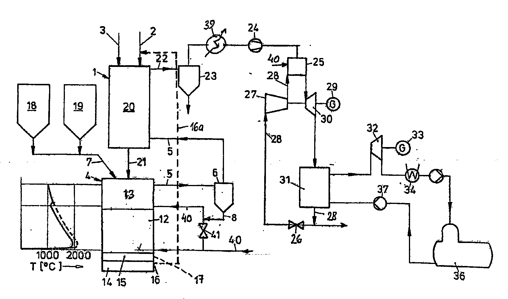
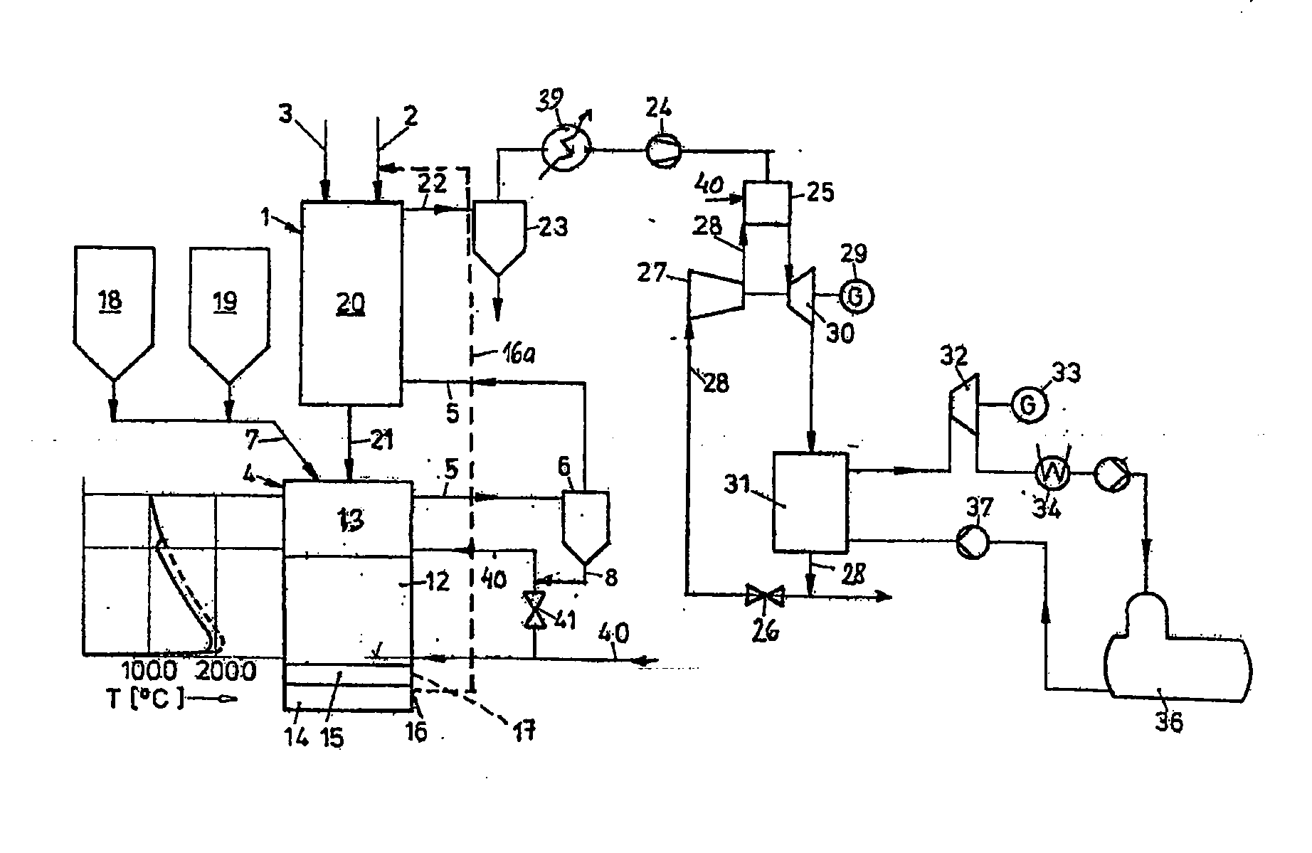
[0095]FIG. 1 represents an embodiment of the present invention.

[0096]Ore 2 and additives 3, such as lime, are fed into the moving bed reactor 1 by means of feeding devices. The charge 20 formed in this way is pre-heated in countercurrent with the dedusted gas from the cyclone 6, partly calcined and partly reduced. After that, this (partly) reduced charge 21 is fed by means of discharging devices through the free space 13 of the fusion gasifier 4 into its char bed 12. This char bed 12 is formed by high-temperature pyrolysis from carbon carriers 7, which come from the coal bunkers 18, 19, by the hot gasification gases of the nozzles blowing in oxygen 40. In this hot char bed 12, the (partly) reduced charge 21 is completely reduced and calcined and subsequently melted to form pig iron 14 and slag 15. The temperature conditions in the char bed 12 are indicated by way of example in the diagram represented in FIG. 1.

[0097]The pig iron 14 and the slag 15 are tapped off at intervals by way ...


PUM


Abstract

A process for generating electrical energy in a gas and steam turbine (combined cycle) power generating plant with a gasification gas produced from carbon carriers and oxygen-containing gas. Carbon carriers are gasified in a gassing zone with oxygen or a gas containing a large amount of oxygen. Gasification gas produced is passed through a desulfurizing zone containing a desulfurizing agent. Used desulfurizing agent is fed into the gassing zone and drawn off after the formation of a liquid slag. Desulfurized gasification gas is burned in a combustion chamber. The resulting combustion gases H2O and CO2 are introduced into the gas turbine for energy generation. Downstream of the gas turbine, the combustion gases are separated in a steam boiler into water vapor and carbon dioxide. The water vapor is subsequently introduced into a steam turbine. The carbon dioxide is at least partially returned to the combustion chamber for setting the temperature.

Description

[0001]The invention relates to a process for generating electrical energy in a gas and steam turbine (combined cycle) power generating plant with a gasification gas produced from carbon carriers and oxygen-containing gas and also to an installation for carrying out this process.BACKGROUND OF THE INVENTION [0002]Around the middle of the 20th century, the first power generating plants with a gas turbine and downstream waste heat recovery for use in a steam turbine were constructed. They are referred to in the industry as gas and steam turbine power generating plants or as combined cycle power generating plants. All these plants are fuelled by natural gas, which can be converted into mechanical energy with satisfactory efficiency in gas turbines. The high purity of the natural gas also makes it possible for them to be operated without any major corrosion problems, even at the high blade temperatures of the turbine. The hot waste gas of the steam turbine is used in a downstream steam bo...

Claims


Application Information

Patent Timeline
IPC IPC(8): F01K23/06F02C6/00
CPCF01K23/067Y02E20/16Y02E20/18Y02E20/32F01K23/06F01K27/00F02C6/18
Inventor KEPPLINGER, LEOPOLD WERNER
Owner SIEMENS VAI METALS TECHNOLOGIES GMBH & CO
Why Eureka
Try Eureka