
Thermal Conducting Materials for Solar Panel Components

a technology of solar panel components and conducting materials, which is applied in the direction of packaging, domestic applications, synthetic resin layered products, etc., can solve the problems of significant reduction of electrical power output, and achieve the effects of improving efficiency, increasing power output, and high thermal conductivity

Inactive Publication Date: 2010-02-25
BP CORP NORTH AMERICA INC
View PDF16 Cites 58 Cited by
  • Summary
  • Abstract
  • Description
  • Claims
  • Application Information

AI Technical Summary

Benefits of technology

[0009]One aspect of this invention is to use higher thermal conducting materials and / or packaging in the solar panels and solar modules for greater power output, improved efficiency, and / or reduced operating temperatures by transferring heat to the surroundings across and / or through the back or bottom materials and / or layers. There is a need for encapsulants and / or back sheets used in solar panels with higher thermal conductivities than conventional materials, while maintaining sufficient dielectric properties for reliable operation.
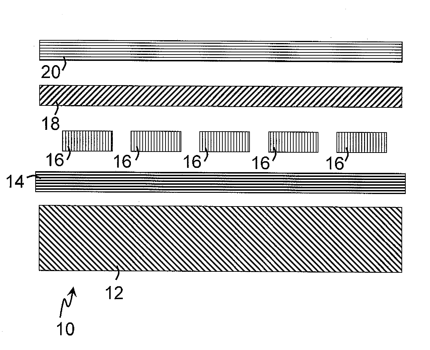
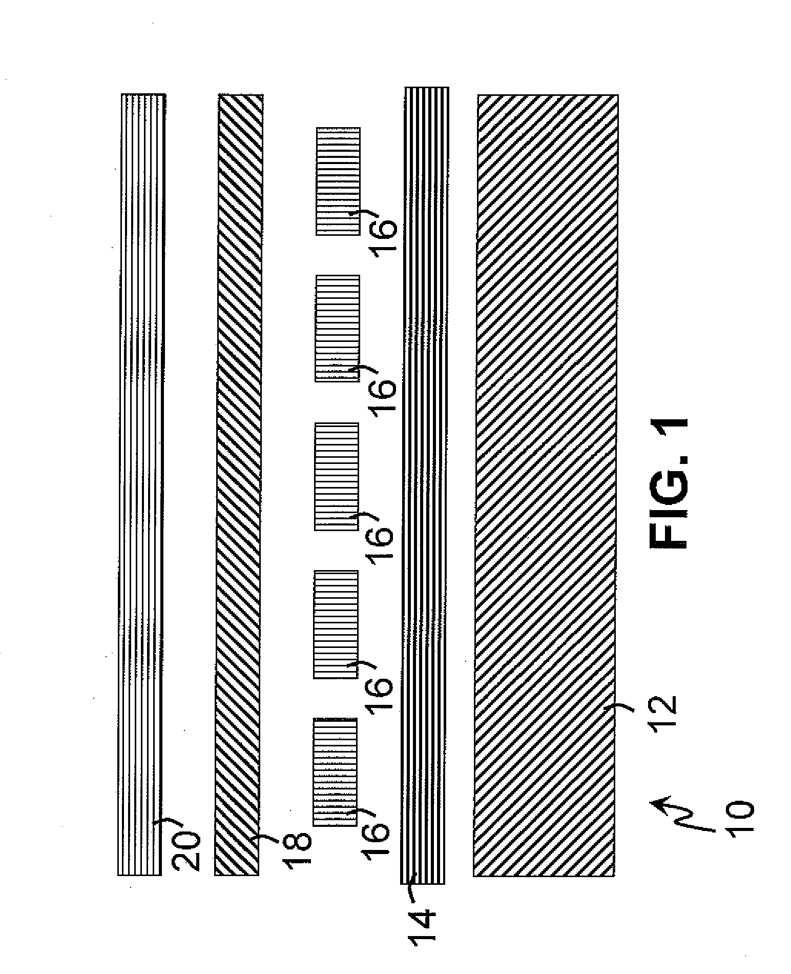
[0017]According to one embodiment, the invention includes a solar module for converting light into electricity. The module includes a transparent front sheet, one or more photovoltaic cells disposed under the transparent front sheet, a back sheet disposed under the one or more photovoltaic cells, and an encapsulant disposed between at least a portion of a back side of the one or more photovoltaic cells and the back sheet. One or both of the back sheet, and / or the encapsulant include an enhanced particle size distribution, a brightening agent, an infrared extinguisher, and / or the like.
[0018]According to one embodiment, the invention includes a process for making a solar module. The process includes the step of providing a transparent front sheet, and the step of placing a first sheet of encapsulant material over at least a portion of the transparent front sheet. The process includes the step of placing one or more photovoltaic cells over the first sheet of encapsulant material, and the step of placing a second sheet of encapsulant material over the one or more photovoltaic cells, the second sheet of encapsulant material with an enhanced particle size distribution, a brightening agent, an infrared extinguisher, and / or the like. The invention includes the step of placing a back sheet over the second sheet of encapsulant material. The back sheet includes an enhanced particle size distribution, a brightening agent, an infrared extinguisher, and / or the like. The process includes the step of laminating the solar module to fuse at least a portion of the first sheet of encapsulant material or the second sheet of encapsulant.

Problems solved by technology

Typically, solar devices are placed in full direct sunlight and as such operate at temperatures above their surroundings due to inefficiencies of conversion and absorption of solar radiation.
Undesirably, these increased operating temperatures of the solar device can significantly reduce the electrical power output.

Method used


Image

  • Thermal Conducting Materials for Solar Panel Components
  • Thermal Conducting Materials for Solar Panel Components
  • Thermal Conducting Materials for Solar Panel Components

Examples


example 1

[0147]A laminated panel was prepared according to comparative Example 1 above except the back side encapsulant was replaced with an ethylene vinyl acetate filled with 15 weight percent silicon carbide having an average particle size of 9 micrometers. The silicon carbide had a CIE L* value of 46.5 according to CIE 1976 (L*, a*, b*) color space. The silicon carbide had a polydispersity (PD) of 0.5. The encapsulant did not include glass scrim. The silicon carbide containing panel was outfitted with a thermocouple and mounted to the backing board as above. The data acquisition and data logging apparatus was configured to record the temperature and voltage of the panel with the silicon carbide filled encapsulant.

[0148]The time of day versus differences (reference minus filled EVA) of the temperatures measured by the respective thermocouples are shown in FIGS. 4-6. FIG. 4 shows the temperature difference being relatively small (less than about 1 degree Celsius) during the early morning an...

example 2

[0151]A second laminated panel was prepared according to comparative Example 1 above except the back side encapsulant was replaced with an ethylene vinyl acetate filled with 15 weight percent talc having a mean particle size of 1.5 micrometers. The talc had a CIE L* value of 77 according to CIE 1976 (L*, a*, b*) color space. The talc had a polydispersity (PD) of 2.3. The encapsulant did not include glass scrim. The talc containing panel was outfitted with a thermocouple and mounted to the backing board as above. The data acquisition and data logging apparatus was configured to record the temperature and voltage of the panel with the talc filled encapsulant.

[0152]FIG. 7 shows data on a still different day with the reference and the talc filled encapsulant panel. The temperature difference peaked earlier in the afternoon and continued to decline with changes in overhead sun. The difference in power averaged over 3 percent. The power difference may be overstated due at least in part to...

example 3

[0153]Thermal calculations based on solar modules with the infrared extinguisher were made. The base case calculations without the extinguisher showed a solar cell operated at 59 degrees Celsius with absorption of the infrared light. The calculations showed that extinguishing 20 percent of the infrared light resulted in a solar module that operated at 57 degrees Celsius or 2 degrees Celsius cooler. The calculations showed that extinguishing 50 percent of the infrared light resulted in a solar module that operated at 55 degrees Celsius or 4 degrees Celsius cooler.

[0154]As used herein the terms “has”, “having”, “comprising”“with”, “containing”, and “including” are open and inclusive expressions. Alternately, the term “consisting” is a closed and exclusive expression. Should any ambiguity exist in construing any term in the claims or the specification, the intent of the drafter is toward open and inclusive expressions.

[0155]As used herein the term “and / or the like” provides support for...


PUM

PropertyMeasurementUnit
Temperatureaaaaaaaaaa
Fractionaaaaaaaaaa
Fractionaaaaaaaaaa

Abstract

This invention relates to solar panels with improved encapsulants and back sheets for greater power output and / or increased efficiency by using materials with higher thermal conductivity than conventional solar panels. According to certain embodiments the improved materials include fillers while maintaining sufficient dielectric properties. According to certain other embodiments, the invention includes a solar panel with the improved encapsulant between solar cells and the improved back sheet. The invention also includes a method of making a solar panel including the improved materials. The invention also includes solar modules and methods related to encapsulants and the back sheets including filler materials with an enhanced particle size distribution, a brightening agent, or an infrared extinguisher.

Description

[0001]This application is a continuation in part and claims the benefit of U.S. Non-Provisional application Ser. No. 12 / 327,246, filed on Dec. 3, 2008 and U.S. Provisional Application No. 61 / 044,618, filed Apr. 14, 2008, the entirety of both are expressly incorporated herein by reference.[0002]This invention was made with U.S. Government support under Cooperative Agreement No. DE-FC36-07G017049 under prime contract with the National Renewable Energy Laboratory awarded by the Department of Energy. The Government has certain right in this invention.BACKGROUND[0003]1. Field of the Invention[0004]This invention relates to the use of higher thermal conducting materials in solar panels and solar modules for improved efficiency, greater power output, and / or reduced operating temperatures.[0005]2. Discussion of Related Art[0006]Conventional photovoltaic collectors or solar devices typically include a plurality of solar cells disposed between a glass substrate and a rear electrically insulat...

Claims


Application Information

Patent Timeline
IPC IPC(8): H01L31/048C09K3/00
CPCB29C65/02Y10T156/10B29C70/58B29C70/70B29K2105/16B29K2995/0012B29K2995/0022B32B17/04B32B17/10018B32B17/10788B32B27/08B32B27/20C08J5/122C08K3/0033C08K5/0041H01L31/048H01L31/052Y02E10/50B29C66/433B29C65/00B32B3/18B32B27/283B32B27/30B32B27/32B32B27/36B32B27/40B32B2262/101B32B2264/10B32B2264/102B32B2264/104B32B2270/00B32B2274/00B32B2307/302B32B2307/4026B32B2307/412B32B2307/7163B32B2457/00C08K3/013H01L31/0488H01L31/049C08J5/18C08K3/00C08L101/12H01L23/29
Inventor XIA, ZHIYONGWOHLGEMUTH, JOHN H.CUNNINGHAM, DANIEL W.
Owner BP CORP NORTH AMERICA INC
Learn More