
Thermoelectric conversion material, method for manufacturing the same, and thermoelectric conversion element

a technology of thermoelectric conversion and thermoelectric elements, which is applied in the direction of silicon, inorganic chemistry, energy-based wastewater treatment, etc., can solve the problems of large amount of produced silicon sludge to be disposed of in landfill to be harmless, large amount of time and cost for treatment, and large amount of fine grain silicon sludge containing various impurities in addition to silicon, etc., to achieve stable and stable thermoelectric conversion performance, high physical strength, and high thermal performan

Inactive Publication Date: 2010-03-04
SHOWA KDE +2
View PDF2 Cites 34 Cited by
  • Summary
  • Abstract
  • Description
  • Claims
  • Application Information

AI Technical Summary

Benefits of technology

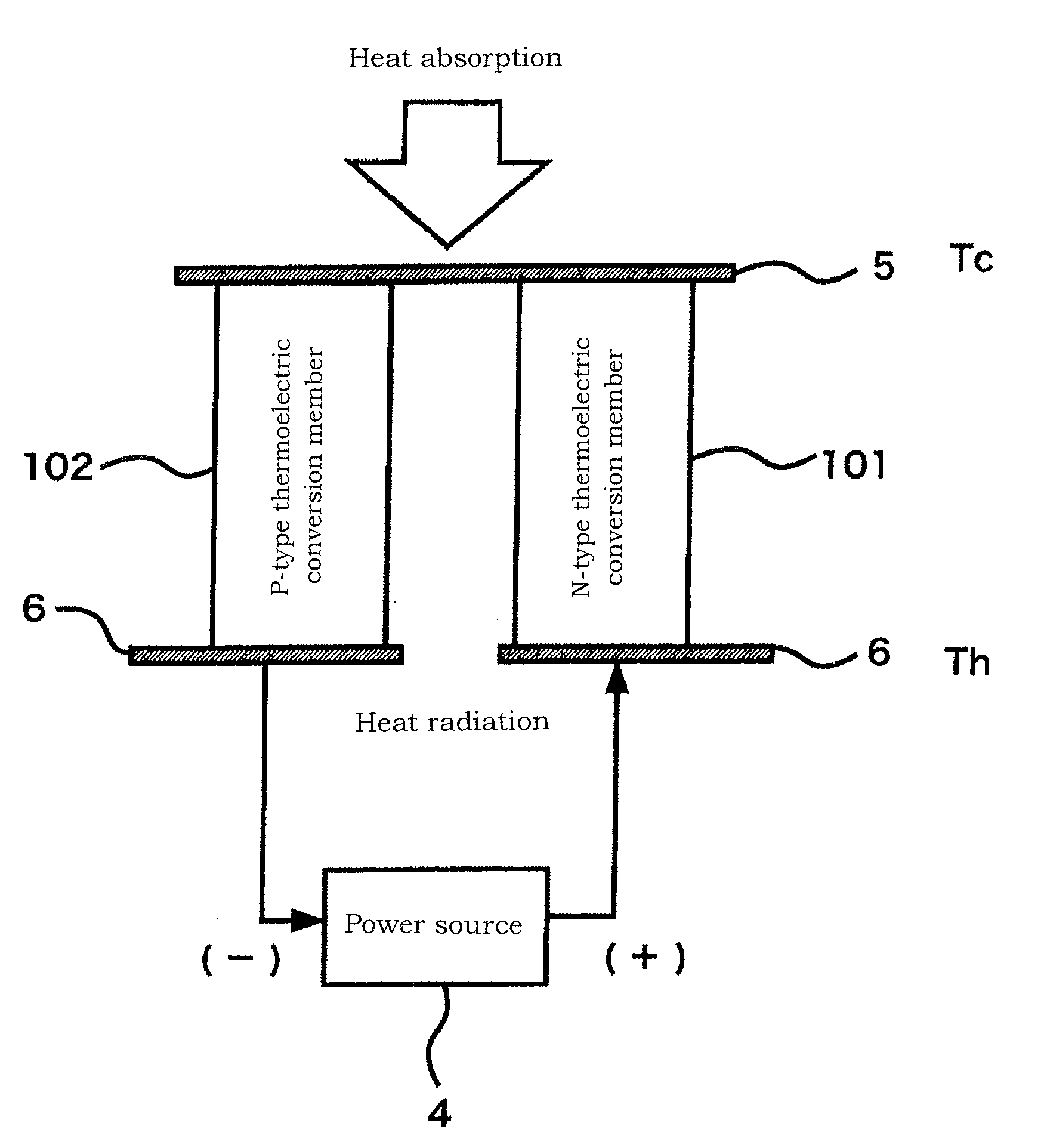
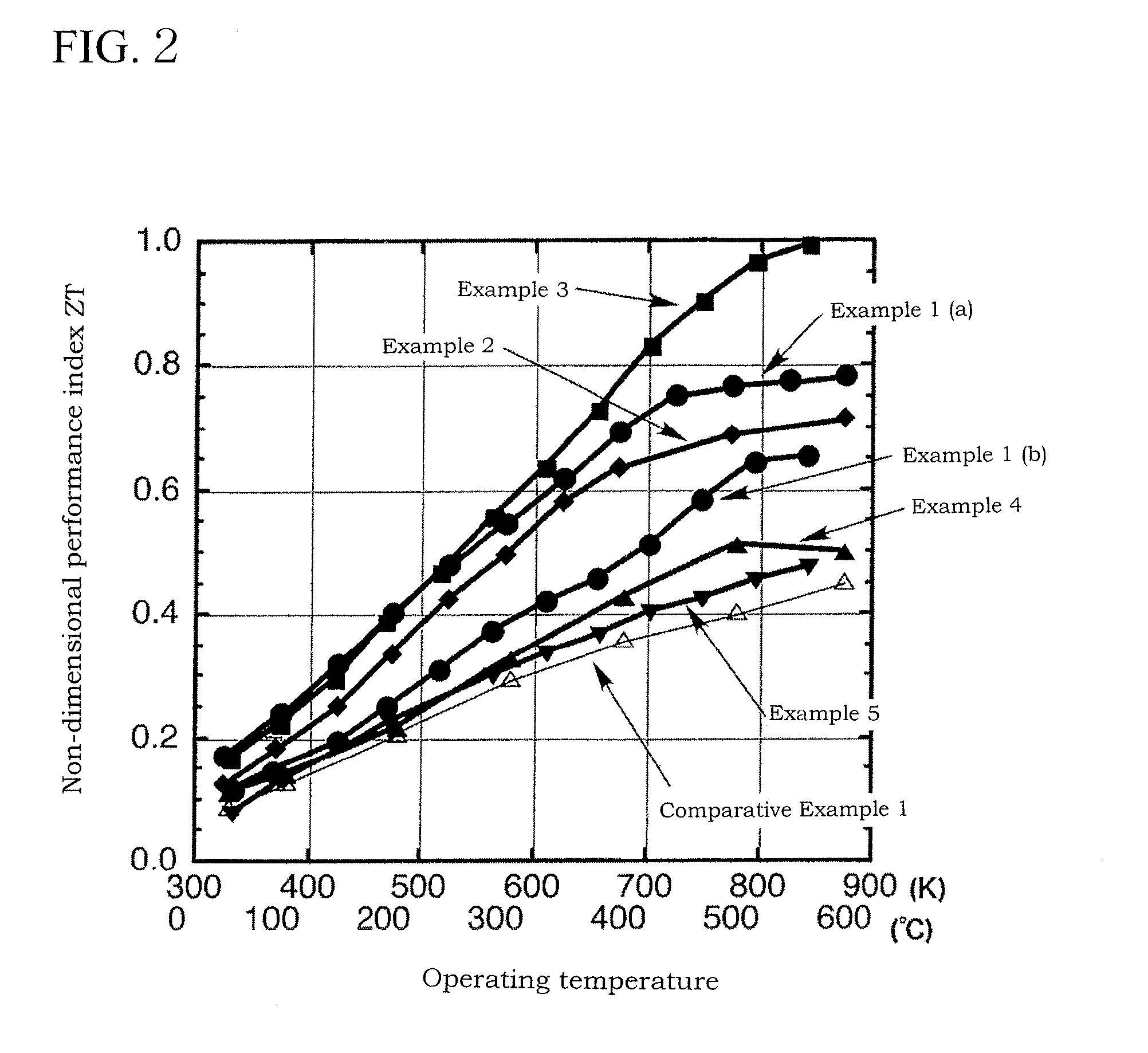
[0072]The thermoelectric conversion material of the invention includes a sintered body composed of, as a main component, magnesium silicide (Mg2Si) containing at least one element selected from As, Sb, P, Al, and B. This thermoelectric conversion material is a silicide-based material with less environmental load and has significant advantages such as high thermoelectric conversion performance stable at about 300 to 600° C., high physical strength, resistance to weathering, durability, stability, and reliability.
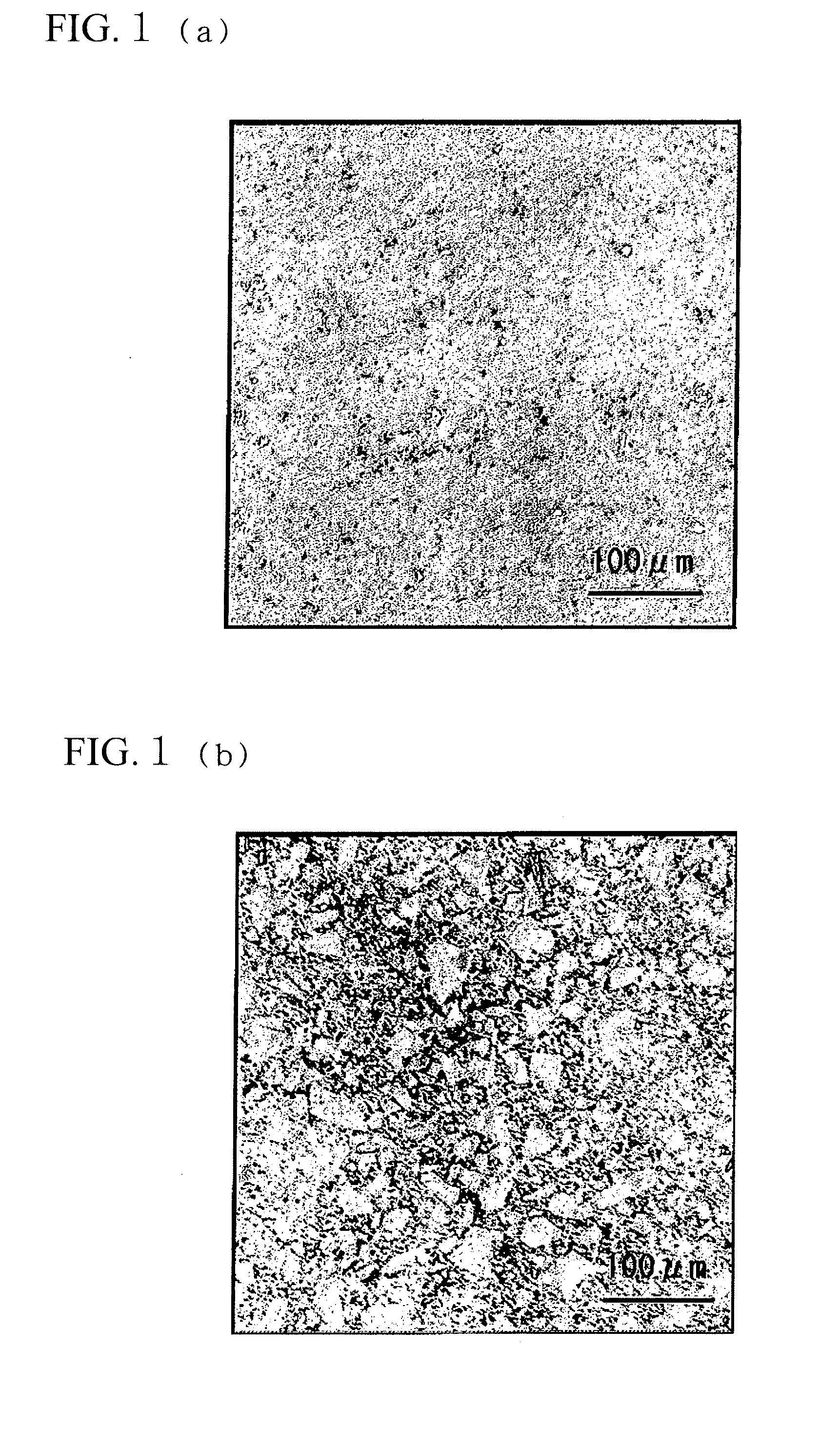
[0113]The thermoelectric conversion material of the invention including a sintered body composed of, as a main component, magnesium silicide (Mg2Si) containing at least one element selected from As, Sb, P, Al, and B is a dense body with few voids in which the magnesium silicide particles are fusion-bonded to each other. In addition, unreacted silicon and magnesium, silicon oxide, and magnesium oxide are not present. Therefore, the thermoelectric conversion material stably exhibits high thermoelectric conversion performance at about 300 to 600° C., and has high physical strength, resistance to weathering, durability, stability, and reliability.

Problems solved by technology

Moreover, a large amount of produced silicon sludge to be disposed of in landfill must be rendered harmless before landfill disposal under the regulation of landfill sites.
Another problem is that the number of available landfill sites is decreasing in recent years.
Such very fine grain silicon sludge containing various impurities in addition to silicon requires a large amount of time and cost for treatment.
In this proposal, the Si particles are dispersed in a non-coagulate state, and therefore a thermoelectric conversion material with stable performance may be difficult to obtain.
However, in medium- and small-scale waste incineration facilities, which are a large majority of waste incineration facilities, electricity generation using a turbine cannot be used because of its high dependency on scale merit.
However, the problem of such materials is that hazardous substances contained therein increase the environmental load.
However, the problem of these materials is that their crystalline phases are decomposed at high temperatures, so that the stability in the high temperature region is poor.
However, these materials are difficult to manufacture because, for example, high chemical reactivity of Mg poses danger.
In addition, there are several problems in that the manufactured materials are not usable because they are brittle and therefore weathered and that the thermoelectric conversion performance is low.Patent Document 1: Japanese Patent No. 3291487.Patent Document 2: Japanese Patent Application Laid-Open No. 2003-200005.Patent Document 3: Japanese Patent Application Laid-Open No. 2003-103267.Patent Document 4: Japanese Patent Application Laid-Open No. 2004-122093.Patent Document 5: Japanese Patent Application Laid-Open No.

Method used


Image

  • Thermoelectric conversion material, method for manufacturing the same, and thermoelectric conversion element
  • Thermoelectric conversion material, method for manufacturing the same, and thermoelectric conversion element
  • Thermoelectric conversion material, method for manufacturing the same, and thermoelectric conversion element

Examples


example 1

[0223]Waste silicon sludge produced in the dicing step of a semiconductor assembling process performed in a semiconductor manufacture was subjected to filtration-separation treatment using a collecting apparatus (Aqua Closer, product of SANYO Electric Co., Ltd.) and a filter press (product of PARKER ENGINEERING CO., LTD.), whereby class 3 silicon sludge having a silicon concentration of 95 mass % and a water content of 5 mass % was obtained. The class 3 silicon sludge was subjected to analysis and confirmed to contain B in a concentration of 100 ppm and p in a concentration of 1,000 ppm.

[0224]Next, the dewatering step in the purifying and refining step was performed. The class 3 silicon sludge was placed in a commercial electric furnace. The sludge was then subjected to heat treatment at 250° C. in air for 3 hours while argon gas containing 5 percent by volume of hydrogen gas was supplied at 3000 L / min to thereby remove water.

[0225]Subsequently, the silicon oxide eliminating step in...

example 2

[0243]Waste silicon sludge produced in a wafer processing process (mirror polishing and back grinding steps) performed in a semiconductor manufacture was subjected to filtration-separation treatment to prepare sludge having a silicon concentration of 92 mass % and a water content of 8 mass %. The analysis revealed that the prepared sludge was class 2 silicon sludge having a B concentration of 6 ppm and a P concentration of 70 ppm.

[0244]The same procedure as in Example 1 was followed except that the obtained sludge was used and a sintering pressure of 30 MPa was used to give a sintered body (not doped).

[0245]The obtained sintered body was analyzed in the same manner as in Example 1. The results showed that the sintered body contained 90 ppm of Al originating from the Al2O3-made melting crucible, 240 ppm of As, 8 ppm of P, and 4 ppm of B.

[0246]The density of the obtained sintered body was 99% of the theoretical density.

[0247]The non-dimensional performance index ZT of the obtained sin...

example 3

[0249]Waste silicon sludge produced in a wafer processing process (mirror polishing and back grinding steps) performed in a semiconductor manufacture was subjected to filtration-separation treatment to prepare sludge having a silicon concentration of 92 mass % and a water content of 8 mass %. The analysis revealed that the prepared sludge was class 2 silicon sludge having a B concentration of 6 ppm and a P concentration of 70 ppm.

[0250]Next, the dewatering step in the purifying and refining step was performed. The silicon sludge was subjected to heat treatment in a commercial electric furnace at 250° C. in air for 3 hours while argon gas containing 5 percent by volume of hydrogen gas was supplied at 3000 L / min to thereby remove water.

[0251]Subsequently, the silicon oxide eliminating step in the purifying and refining step was performed. The dewatered silicon sludge was heat-treated in the same electric furnace at 500° C. in air under reduced pressure for 2 hours while argon gas cont...


PUM

PropertyMeasurementUnit
Temperatureaaaaaaaaaa

Abstract

A thermoelectric conversion material is provided which stably exhibits high thermoelectric conversion performance at about 300 to 600° C. and has high physical strength, resistance to weathering, durability, stability, and reliability. A method for manufacturing the same, and a thermoelectric conversion element are also provided. Also provided is a thermoelectric conversion material produced using, as a raw material, silicon sludge which has had to be disposed of in landfill. The thermoelectric conversion material of the invention is characterized by containing, as a main component, a sintered body composed of polycrystalline magnesium silicide containing at least one element selected from As, Sb, P, Al, and B. The manufacturing method uses purified and refined silicon sludge.

Description

TECHNICAL FIELD[0001]The present invention relates to a thermoelectric conversion material, to a method for manufacturing the same, and to a thermoelectric conversion element.BACKGROUND ART[0002]Waste silicon sludge is produced when silicon ingots and wafers composed of high-purity silicon used to manufacture silicon products such as semiconductors and solar cells are ground and polished. Such silicon sludge has a very small particle size of 0.1 to 10 μm and contains, in addition to silicon, boron, phosphorus, tungsten, chromium, titanium, arsenic, gallium, iron, oxygen, and other materials that have been implanted as impurities into the surface of the wafers by ion implantation. The silicon sludge further contains polyaluminum chloride and aluminum sulfate that are used as flocculants added to flocculate and precipitate the silicon sludge.[0003]Moreover, water is used to improve the lubricity during grinding and polishing. However, since oil and other materials are added to the wat...

Claims


Application Information

Patent Timeline
IPC IPC(8): H01L35/20H01L35/34
CPCB09B3/005H01L35/34C04B35/62204C04B35/6261C04B35/6263C04B35/6265C04B35/62655C04B35/62665C04B35/6268C04B35/645C04B35/6455C04B2235/40C04B2235/401C04B2235/402C04B2235/42C04B2235/421C04B2235/428C04B2235/5427C04B2235/5436C04B2235/5445C04B2235/652C04B2235/6581C04B2235/666C04B2235/72C04B2235/725C04B2235/727C04B2235/77C04B2235/79C04B2235/81H01L35/22C04B35/58085Y02W10/37B09B3/29H10N10/855H10N10/01C02F11/00C04B35/00C04B35/58H10N10/854
Inventor IIDA, TSUTOMUMITO, YOHIKONEMOTO, TAKASHI
Owner SHOWA KDE
Learn More