
Process for producing dispersible and conductive Nano Graphene Platelets from non-oxidized graphitic materials

Active Publication Date: 2010-03-04
GLOBAL GRAPHENE GRP INC
View PDF19 Cites 96 Cited by
  • Summary
  • Abstract
  • Description
  • Claims
  • Application Information

AI Technical Summary

Benefits of technology

[0125]It may be noted that although Kaschak, et al. [76] proposed a method of modifying graphite by introducing a supercritical fluid into interstices of graphite flake, the graphite flake used was intercalated or intercalated / oxidized graphite (rather than the original natural graphite). The interstices of intercalated / oxidized graphite had been expanded and chemically modified due to the presence of intercalant species (such as sulfuric acid) or oxidation-induced functional groups (such as carboxyl). Kaschak, et al. did not teach the approach of directly intercalating natural (un-treated) graphite flake with a supercritical fluid; nor did they teach the approach of intercalating and exfoliating graphite using the same supercritical fluid. The modified graphite as proposed by Kaschak, et al. [76] still required a high temperature exposure step, typically at 700-1,200° C., to exfoliate the intercalated and modified graphite. Furthermore, they really did not provide any evidence to show the existence of nano-scaled graphite particles that they claimed they produced with this method. In particular, they claimed that “one advantage of the invention is that the aforementioned methods may be used to manufacture graphite in a form that has a thickness of less than about 10 microns, preferably less than about 1 micron, more preferably less than about 100 nm, even more preferably less than about 10 nm, and most preferably less than about 1 nm.” However, they did not fairly suggest the conditions under which graphite particles with a thickness less than 10 nm or 1 run could be produced. This was truly a big claim and should have been supported by solid experimental evidence; unfortunately, absolutely no evidence whatsoever was presented.

Problems solved by technology

Furthermore, the reduction procedure often involves the utilization of undesirable chemicals, such as hydrazine.
These films were exposed to a high temperature, high vacuum environment for de-oxygenation, but the resulting GO platelets were no longer dispersible in water or other solvents.
However, unless stabilized by selected polymers, the chemically modified graphene sheets obtained through these methods tend to precipitate as irreversible agglomerates due to their hydrophobic nature.
This is a very tedious process, nevertheless.(p) Another very tedious process for the preparation of GO nano sheets, proposed by Becerril, et al.
Unfortunately, Shioyama did not discuss the thickness of the isolated graphene sheets.(s) Jang, et al.
The process must be carefully conducted in a vacuum or an extremely dry glove box environment since pure alkali metals, such as potassium and sodium, are extremely sensitive to moisture and pose an explosion danger.
It is questionable if this process is easily amenable to the mass production of nano-scaled platelets.
This is a slow process that thus far has produced very small graphene sheets.
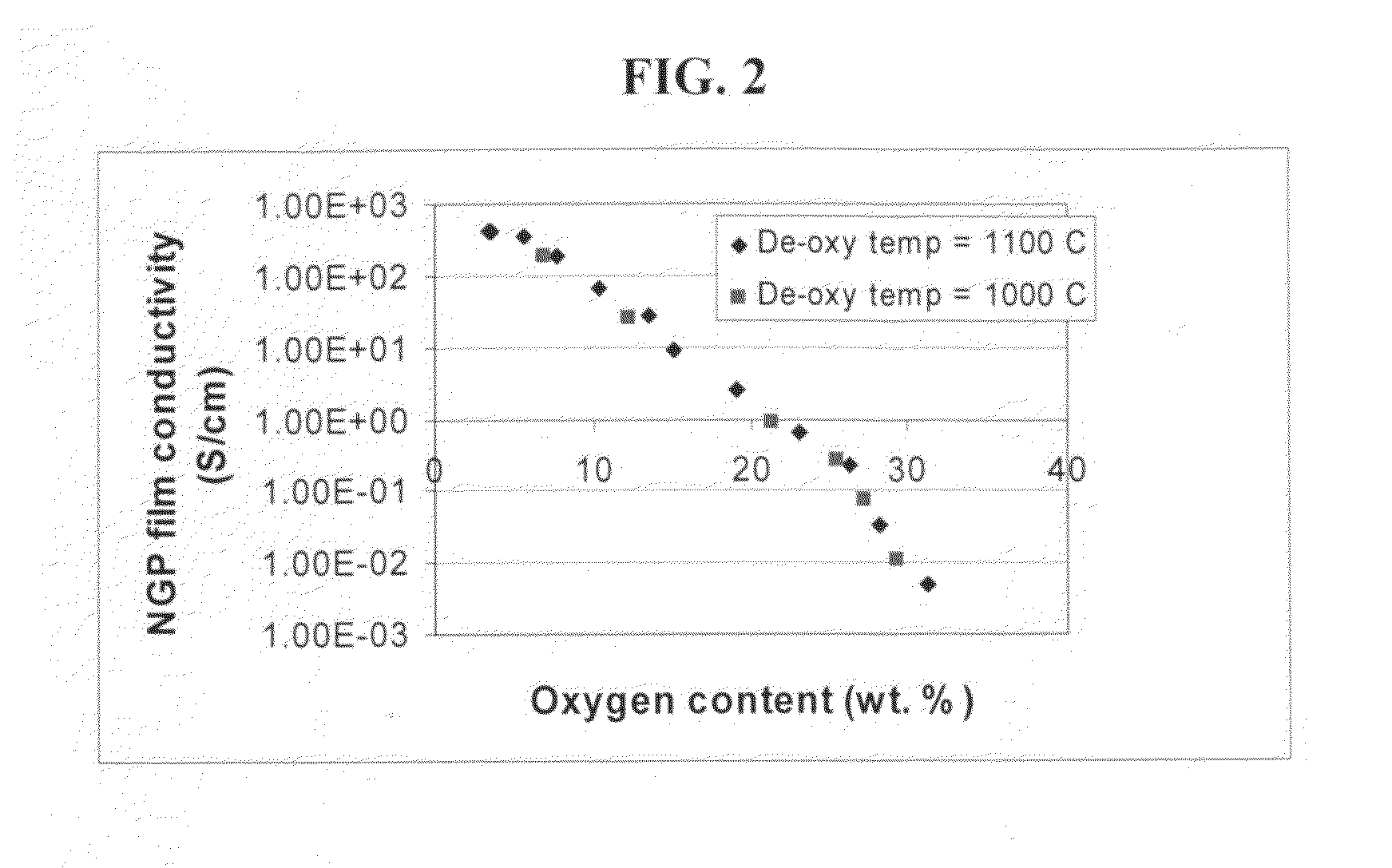
There are several major issues associated with the aforementioned processes:(1) The GO nano platelets prepared by Approach 1, albeit dispersible in water and several other polar liquids such as ethanol and acetone, are not dispersible in a wide range of organic solvents.(2) The GO nano platelets exhibit an electrical conductivity typically several orders of magnitude lower than the conductivity of pristine NGPs.
However, pristine NGPs, just like reduced GO platelets, are typically not soluble or dispersible in water or other organic solvents.
It is also difficult to homogeneously mix or disperse pristine NGPs in a polymer matrix.
These features make it difficult to fabricate nanocomposite parts with good filler dispersion or good filler-matrix interfacial bonding, which are essential to the realization of good composite properties.

Method used


Image

  • Process for producing dispersible and conductive Nano Graphene Platelets from non-oxidized graphitic materials
  • Process for producing dispersible and conductive Nano Graphene Platelets from non-oxidized graphitic materials
  • Process for producing dispersible and conductive Nano Graphene Platelets from non-oxidized graphitic materials

Examples


example 1

NGPs From Carbon / Graphite Fibers

[0176]Continuous graphite fiber yarns (Magnamite from Hercules) were cut into segments of 5 mm long and then ball-milled for 24 hours. Approximately 20 grams of these milled fibers were immersed in a mixture of 2 L of formic acid and 0.1 L of hydrogen peroxide at 45° C. for 48 hours. Following the chemical oxidation intercalation treatment, the resulting intercalated fibers were washed with water and dried. The resulting product is a formic acid-intercalated graphite fiber material containing graphite oxide crystallites.

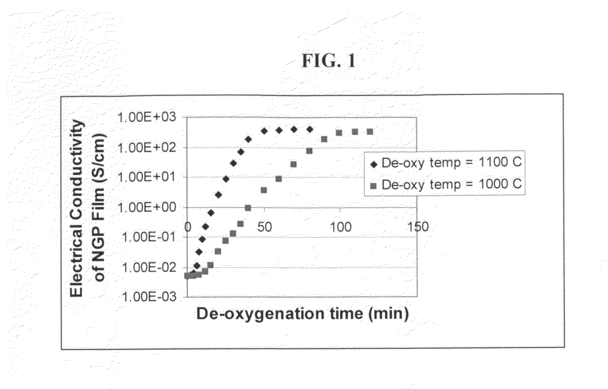
[0177]Subsequently, approximately ½ of the intercalated or oxidized fiber sample was transferred to a furnace pre-set at a temperature of 600° C. for 30 seconds. The compound was found to induce extremely rapid and high expansions of graphite crystallites. The as-exfoliated graphite fiber is designated as Sample-1a. Approximately half of Sample 1-a material was subjected to de-oxygenation at 1,100° C. for 20 minutes in a nitrogen atmos...

example 2

NGPs From Sulfuric Acid Intercalation and Exfoliation / De-Oxygenation of MCMBs

[0180]MCMB 2528 microbeads were supplied by Alumina Trading, which is the U.S. distributor for the supplier, Osaka Gas Chemical Company of Japan. This material has a density of about 2.24 g / cm3; a particle size maximum for at least 95% by weight of the particles of 37 microns; median size of about 22.5 microns and an inter-planar distance of about 0.336 nm. MCMB 2528 (10 grams) were intercalated with an acid solution (sulfuric acid, nitric acid, and potassium permanganate at a ratio of 4:1:0.05) for 24 hours. Upon completion of the reaction, the mixture was poured into deionized water and filtered. The intercalated MCMBs were repeatedly washed in a 5% solution of HCl to remove most of the sulphate ions. The sample was then washed repeatedly with deionized water until the pH of the filtrate was neutral. The slurry was spray-dried and stored in a vacuum oven at 60° C. for 24 hours. The dried powder sample was...

example 3

Oxidation, Exfoliation, and De-Oxygenation of Natural Graphite

[0181]Graphite oxide was prepared by oxidation of graphite flakes with sulfuric acid, sodium nitrate, and potassium permanganate at a ratio of 4:1:0.05 at 30° C. for 24 hours, according to the method of Hummers [U.S. Pat. No. 2,798,878, Jul. 9, 1957]. Upon completion of the reaction, the mixture was poured into deionized water and filtered. The sample was then washed with 5% HCl solution to remove most of the sulfate ions and residual salt and then repeatedly rinsed with deionized water until the pH of the filtrate was approximately 7. The intent was to remove all sulfuric and nitric acid residue out of graphite interstices. The slurry was spray-dried and stored in a vacuum oven at 60° C. for 24 hours. The interlayer spacing of the resulting laminar graphite oxide was determined by the Debey-Scherrer X-ray technique to be approximately 0.73 nm (7.3 Å), indicating that graphite has been converted into graphite oxide.

[0182]...


PUM

PropertyMeasurementUnit
Fractionaaaaaaaaaa
Percent by massaaaaaaaaaa

Abstract

The present invention provides a process for producing nano graphene platelets (NGPs) that are both dispersible and electrically conducting. The process comprises: (a) preparing a pristine NGP material from a graphitic material; and (b) subjecting the pristine NGP material to an oxidation treatment to obtain the dispersible NGP material, wherein the NGP material has an oxygen content no greater than 25% by weight. Conductive NGPs can find applications in transparent electrodes for solar cells or flat panel displays, additives for battery and supercapacitor electrodes, conductive nanocomposite for electromagnetic wave interference (EMI) shielding and static charge dissipation, etc.

Description

FIELD OF THE INVENTION[0001]The present invention relates generally to the field of carbon- or graphite-based nano materials, and more particularly to nano graphene platelets (NGPs), including their oxidized versions (graphite oxide nano platelets), that are soluble or dispersible in a liquid medium or a matrix material.BACKGROUND OF THE INVENTION[0002]The present discussion of the prior art will make reference to the patent literature and technical papers listed at the end of this section.[0003]The nanoscale graphene platelet (NGP) or graphene nano-sheet is an emerging class of nano materials. An NGP is a nanoscale platelet composed of one or more layers of a graphene plane, with a platelet thickness from less than 0.34 nm to 100 nm. In a graphene plane, carbon atoms occupy a 2-D hexagonal lattice in which carbon atoms are bonded together through strong in-plane covalent bonds. In the c-axis or thickness direction, several graphene planes may be weakly bonded together through van d...

Claims


Application Information

Patent Timeline
IPC IPC(8): C01B31/02C07F7/08C07C211/43C07C315/00C07C45/27C07C33/00C07C25/00
CPCB82Y30/00C01B31/0206B82Y40/00Y10S977/755Y10S977/775C01B32/15
Inventor JANG, BOR Z.ZHAMU, ARUNA
Owner GLOBAL GRAPHENE GRP INC
Learn More