Downhole telemetry apparatus and method

a telemetry apparatus and downhole technology, applied in the direction of survey, directional drilling, borehole/well accessories, etc., can solve the problems of wasting costs, difficulty in knowing with reasonable accuracy where the drill bit is, loss of production revenue, etc., and achieve the effect of facilitating transmission from the signal sending devi

Active Publication Date: 2010-03-18
ZIENTARSKI MARIUSZ THOMAS
View PDF6 Cites 14 Cited by
  • Summary
  • Abstract
  • Description
  • Claims
  • Application Information

AI Technical Summary

Benefits of technology

[0029]In another feature of that aspect of the invention, the carrier current has a current magnitude that is more than 100 times as large as the peak current magnitude of the electrical signal. In another feature the carrier current has a value of greater than 0.5 amps. In still another feature the method includes employing a power supply adjacent to the well head to supply power for the carrier current. In a still further feature, the method includes building up a stored charge in the geological formation adjacent to the drill bit. In yet another feature the method includes discharging the geological formation through the drillstring, and placing the electrical signal on an electrical discharge current associated with that discharge.
[0030]In another aspect of the invention there is a method of obtaining data from a signal sending device in a downhole location in a well bore, wherein the signal sending device has an electrical signal generator, and the method includes providing power from a source remote from the downhole location to facilitate transmission from the signal sending device.

Problems solved by technology

Given the non-homogeneity of the underlying geological structure, and the tendency for drill bits to wander, it may be difficult to know with reasonable accuracy where the drill bit may be.
(a) The drilling operation, and mud motor life, may be optimized by the real time transmission of, and adjustment of drilling operations in response to, measurement data of natural gamma rays, borehole inclination, borehole pressure, resistivity of the formation and, mud motor bearing temperature, and weight on the bit.
(b) When used with a downhole motor, the mud pulse telemetry system is typically located above the mud motor so that it is spaced a substantial distance from the drilling bit to protect the electronic components from the effects of vibration. As a result, the measured environmental data may not necessary correlate with the actual conditions at the drilling bit. A conventional telemetry system may have a depth lag (i.e., a distance offset) of up to or greater than 60 feet. It is possible to drill out of a hydrocarbon producing formation before detecting the exit, resulting in the need to drill several meters of borehole to get back into the pay zone. The interval drilled outside of the pay zone results in lost production revenue and may include wasted costs for completing that non-producing interval.
(c) Near bit sensor systems have been developed to provide early detection of changes to the formation while drilling, but may still be located a spaced distance from the drill bit assembly, giving a lag in determination of formation changes. Mounting sensors in a mud motor may be very costly and may reduce system reliability.
(d) Systems permitting relatively high rate, bi-directional, data transmission have been developed for sending data to the surface through an electrical line. However, a drill string wireline or cable is subject to stress at pipe connections; may be prone to wear, damage or destruction during normal drilling operations; and may be somewhat unreliable and prone to failure.
(e) Systems have also been developed for the downhole generation and transmission of acoustic or seismic signals or waves through the drill string or surrounding formation. However, a relatively large amount of downhole power is typically required to generate sufficient signal strength for surface detection. A relatively large power source must be provided or repeaters can be used at intervals along the string to boost the signal as it propagates.
The optimal placement of the borehole is thus very difficult to obtain based on the currently available MWD measurements, particularly in thin pay zones, dipping formation and complex wellbore designs.”
It is well known that mud pulse systems are intrinsically limited to a few bits per second due to attenuation and spreading of pulses.”
It has been found, however, that this type of system requires a special drill pipe and special tool joint connectors which substantially increase the cost of a drilling operation.
Also, these systems are prone to failure as a result of the abrasive conditions of the mud system and the wear caused by the rotation of the drill string.”
It has been found, how ever, that the very low intensity of the signal which can be generated downhole, along with the acoustic noise generated by the drilling system, makes signal detection difficult.
Reflective and refractive interference resulting from changing diameters and thread makeup at the tool joints compounds the signal attenuation problem for drill pipe transmission.”
It has been found, however, that in deep or noisy well applications, conventional electromagnetic systems are unable to generate a signal with sufficient intensity to be recovered at the surface.”
As the ratio drops, it becomes more difficult to recover or reconstruct the signal.
While increasing the power of the transmitted signal is an obvious way of increasing the signal to noise ratio, this approach is limited by batteries suitable for the purpose and the desire to extend the time between battery replacements.

Method used


Image

  • Downhole telemetry apparatus and method
  • Downhole telemetry apparatus and method
  • Downhole telemetry apparatus and method

Examples


Embodiment Construction

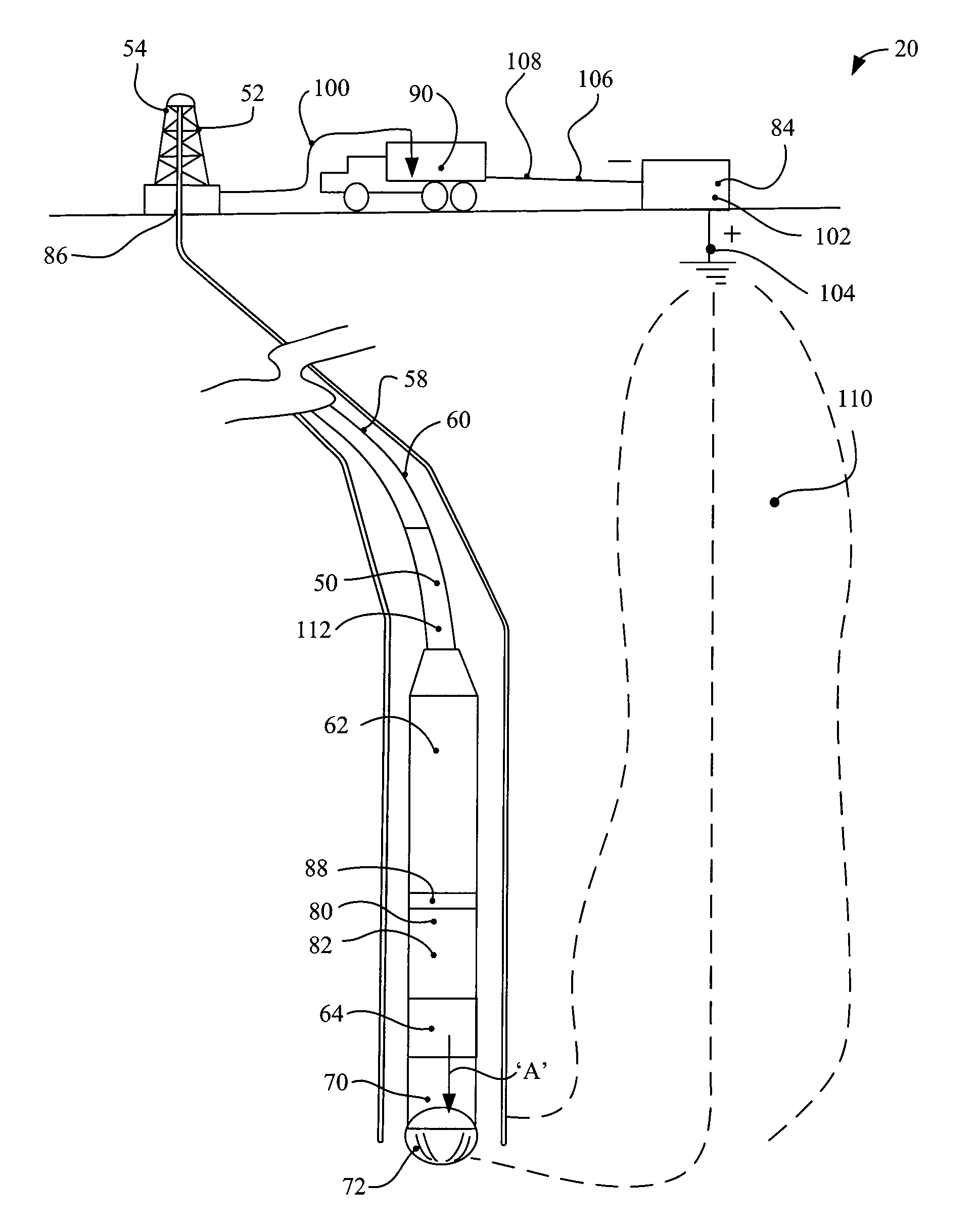
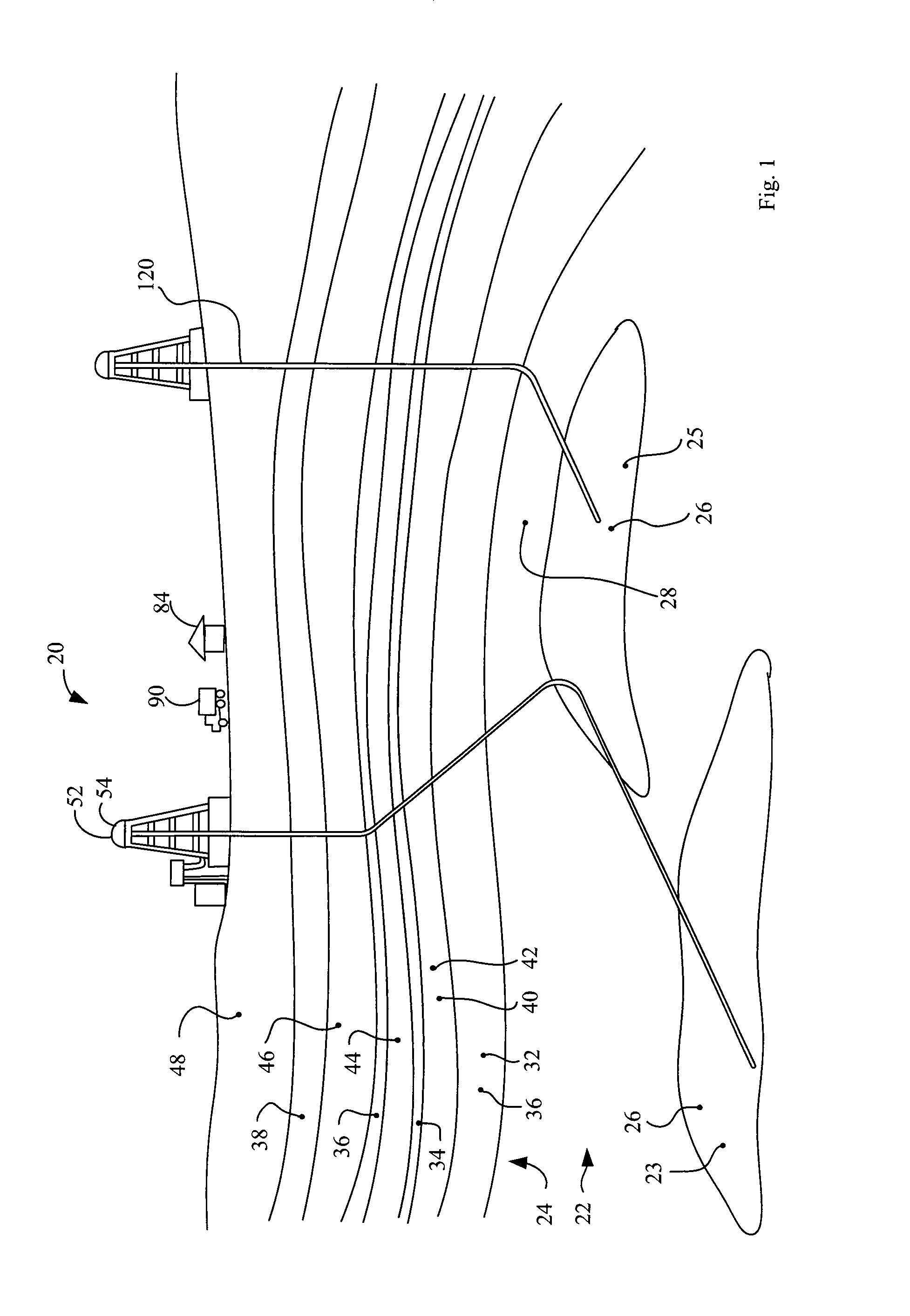
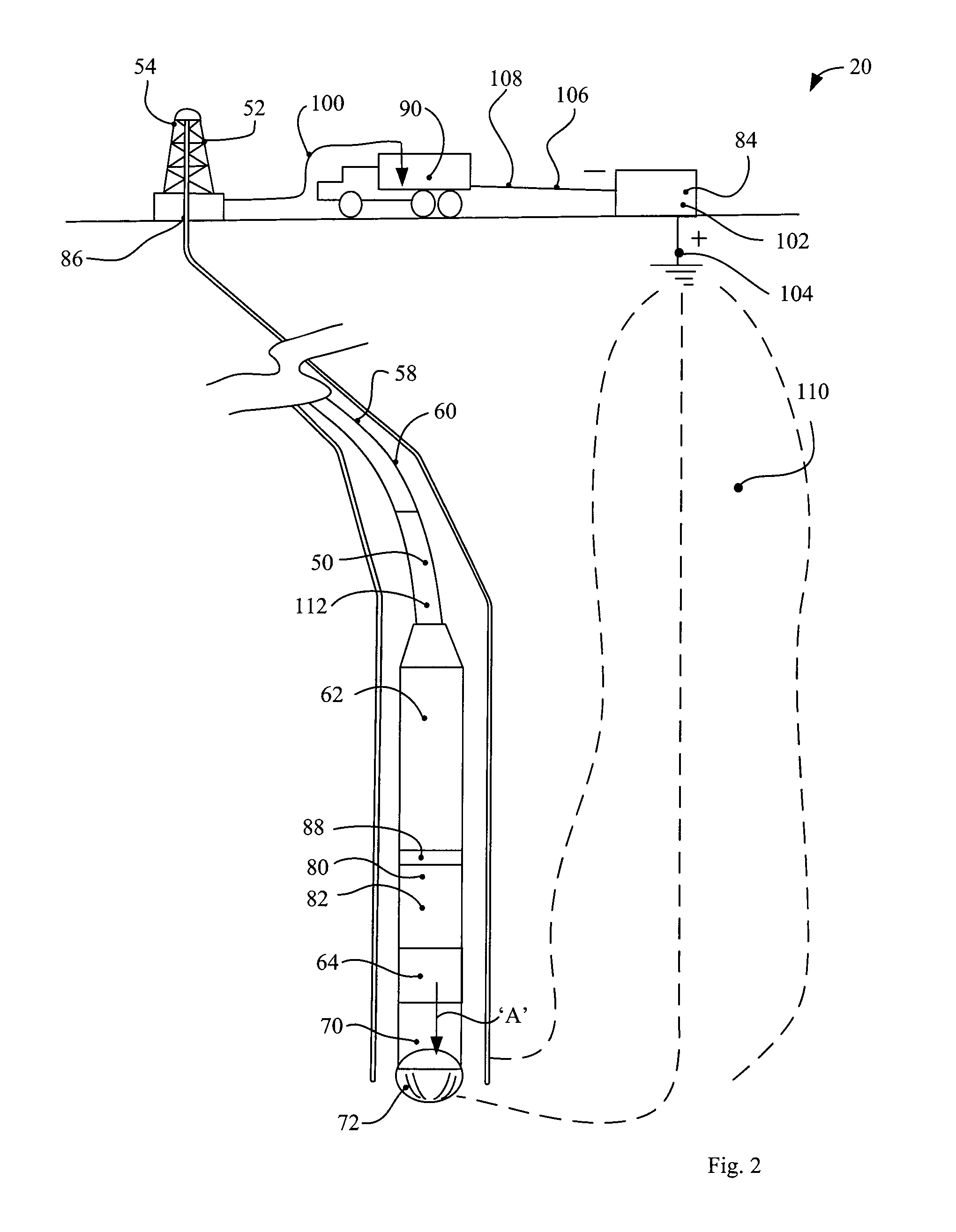
[0036]The description that follows, and the embodiments described therein, are provided by way of illustration of an example, or examples, of particular embodiments of the principles of the present invention. These examples are provided for the purposes of explanation, and not of limitation, of those principles and of the invention. In the description, like parts are marked throughout the specification and the drawings with the same respective reference numerals. The drawings are not necessarily to scale.

[0037]The terminology used in this specification is thought to be consistent with the customary and ordinary meanings of those terms as they would be understood by a person of ordinary skill in the art in North America. Following from the decision of the Court of Appeal for the Federal Circuit in Phillips v. AWH Corp., and while not excluding interpretations based on other sources that are generally consistent with the customary and ordinary meanings of terms or with this specificat...


PUM


Abstract

A telemetry tool is placed in a drill string adjacent to a drill bit. The telemetry tool includes position and direction sensors, a power supply, a signal receiver and a signal emitter. An external base unit, may be mounted on the surface at some distance from the wellhead. The external base unit generates, and transmits into the geological formation, a carrier signal. The carrier signal may be a DC carrier signal, and it may be a variable DC signal.
The base unit also has a receiving unit, which may have the opposite DC voltage to that of the carrier signalemitting unit. The geological formation provides a large current path between the carrier current generating unit and the downhole end of the drill string. The carrier current, or some portion thereof, is received at the telemetry unit. The drill string defines a relatively low resistance conductor for the return signal. Thus a circuit is established from the base unit, through the geological formation to the telemetry unit, and back up the drill string to end back at the base unit.
The telemetry unit superimposes a time varying signal on the carrier current. The time varying signal includes a recognition sequence, followed by a data string. The data string may include information pertaining to compass direction, azimuth dip, rotational speed, acceleration in any of three axes, and so on.
The base unit strips the signal off the carrier current, and reads the code. This system may tend to permit the telemetry tool to operate at relatively low power. The relatively higher power carrier current is provided by the base unit.

Description

FIELD OF THE INVENTION[0001]This invention relates to the field of downhole telemetry apparatus, and methods of use of such apparatus.BACKGROUND[0002]The determination of the location of a distant subterranean object may be of considerable commercial importance in the fields of well drilling, tunnel boring, pipeline laying under rivers or other surface obstructions, hard rock mining, and so on. In hydrocarbon extraction, a drill string may be 3 to 6 inches in diameter, and yet may extend many thousands of feet into the ground. Given the non-homogeneity of the underlying geological structure, and the tendency for drill bits to wander, it may be difficult to know with reasonable accuracy where the drill bit may be. This issue may tend to have enhanced importance in the context of, for example, directional drilling, where it may be desired to follow a relatively narrow and possibly undulating geological feature, such as a coal seam, a hydrocarbon payzone for oil or gas extraction, an o...

Claims


Application Information

Patent Timeline
Patent Type & Authority Applications(United States)
IPC IPC(8): G01V3/24E21B44/00E21B7/06E21B47/12
CPCG01V11/002E21B47/12
Inventor ZIENTARSKI, MARIUSZ THOMAS
Owner ZIENTARSKI MARIUSZ THOMAS
Why Eureka
Try Eureka