
Cationic conjugated polyelectrolyte electron injection layers altered with counter anions having oxidative properties

a technology of conjugated polyelectrolyte and electron injection layer, which is applied in the direction of organic semiconductor devices, solid-state devices, thermoelectric devices, etc., can solve the problems of order of magnitude differences in device performance, and achieve the effect of increasing the performance of multi-layer polymer light-emitting diodes

Inactive Publication Date: 2010-04-22
RGT UNIV OF CALIFORNIA
View PDF4 Cites 11 Cited by
  • Summary
  • Abstract
  • Description
  • Claims
  • Application Information

AI Technical Summary

Benefits of technology

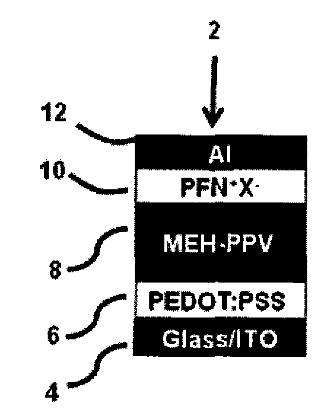
[0008]In one aspect, a method of increasing the performance of a multilayer polymer light emitting diode is provided. The PLED contains an emissive layer and a cationic conjugated polyelectrolyte electron injection layer. The method contains the feature of including a counter anion having oxidative properties in the electron injection layer. In some embodiments of the method, the CPE EIL is a solution processed CPE EIL. In some embodiments of the method, including but not limited to solution processed CPE EIL embodiments, the counter anion undergoes oxidation at the boundary between the emissive layer and CPE EIL. Also, in various embodiments of the method, including but not limited to solution processed CPE EIL embodiments and embodiments where the counter anion undergoes oxidation, the counter anion is selected by considering at least its oxidative properties.
[0010]In another aspect, a method is provided of increasing the performance of a multilayer polymer light emitting diode that contains an emissive layer and a cationic conjugated polyelectrolyte electron injection layer. The method includes preparing a plurality of multilayer polymer light emitting diodes, with each diode containing the cationic conjugated polyelectrolyte electron injection layer and a counter anion included in the electron injection layer. The counter anion is selected by considering at least its oxidative properties, and the counter anion of each diode differs from the counter anion of the other multilayer polymer light emitting diodes. The method also includes determining the performance of the plurality of polymer light emitting diodes to identify one of the diodes that performs better than another of the diodes, which can include identifying one that performs the best of all the diodes. In certain embodiments of the method, the CPE EIL is a solution processed CPE EIL. Also, in some embodiments of the method, including but not limited to solution processed CPE EIL embodiments, the counter anion can be a halide counter anion.

Problems solved by technology

Organic counter ion alteration of CPEs has also been shown to lead to orders of magnitude differences in device performance (12).

Method used


Image

  • Cationic conjugated polyelectrolyte electron injection layers altered with counter anions having oxidative properties
  • Cationic conjugated polyelectrolyte electron injection layers altered with counter anions having oxidative properties
  • Cationic conjugated polyelectrolyte electron injection layers altered with counter anions having oxidative properties

Examples


example 1

Methods and Materials

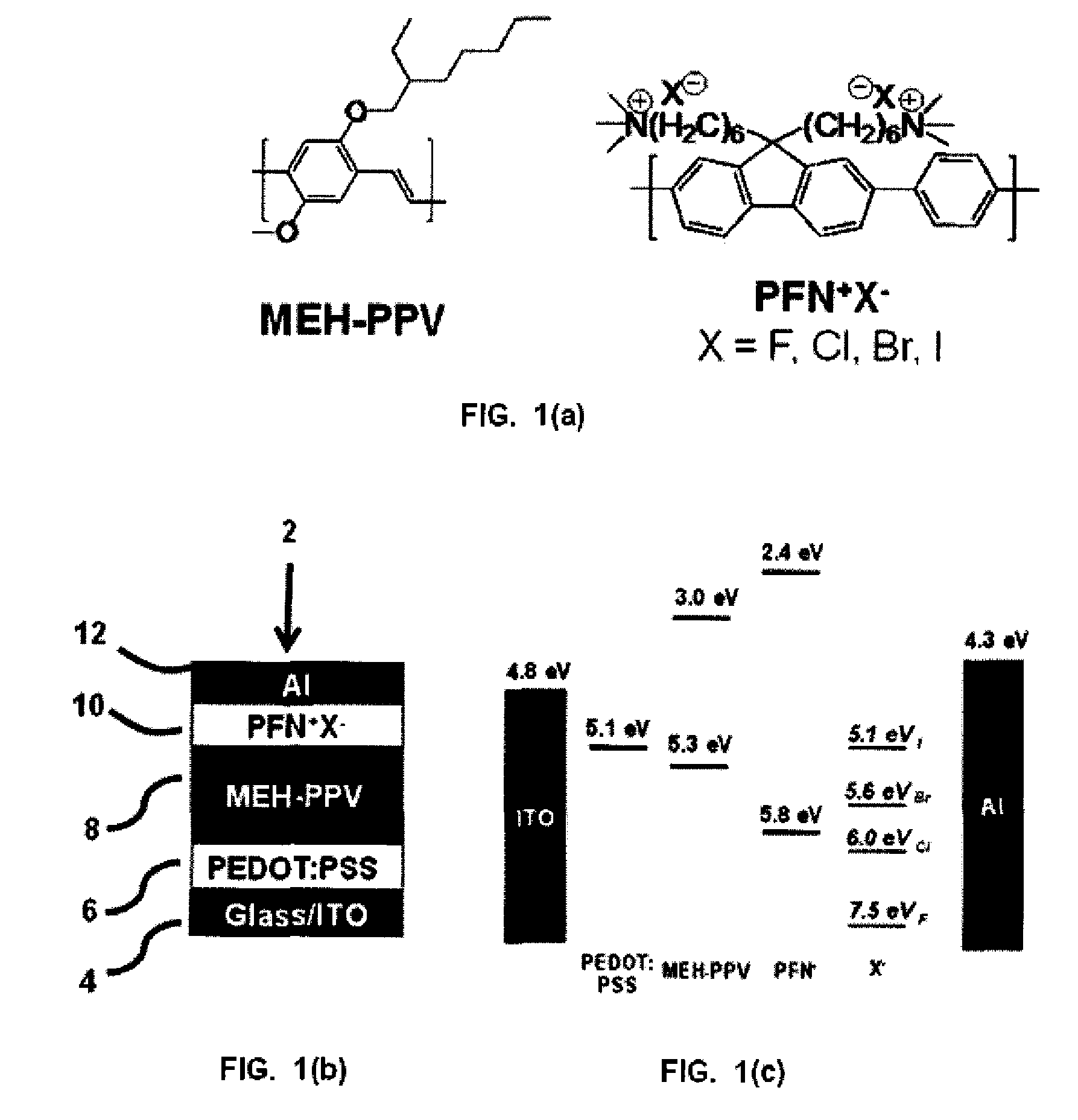
[0032]MEH-PPV (14) and PFN+Br− (15) were synthesized according to previous reports. PFN+F−, PFN+Cl− and PFN+1− were acquired from PEN+Br− ion exchange with dialysis membranes and mixing with the appropriate potassium salt. Cellulose ester dialysis membranes (Spectrum Laboratories, Inc.) with a 1,000 molecular weight cut off were filled with a water solution of PFN+Br− followed by addition of excess amount (5:1 weight) of the appropriate potassium halide salt. The dialysis membrane were immersed in a stirred de-ionized water bath until the osmotic pressure was reduced (˜4 days) when upon more salts were added. This was repeated three times followed by evaporation of water under reduce pressure. Counter ion exchange was confirmed with X-ray photoelectron spectroscopy (XPS) measurements of the powdered CPE samples with a Kratos Axis Ultra XPS system with a base pressure of 1×10⁻¹⁰ mbar (UHV), using a monochromated Al Kα X-ray source at hv=1486 eV. The structures of...

example 2

Materials Characterization

[0036]Devices prepared as in Example 1 were characterized.

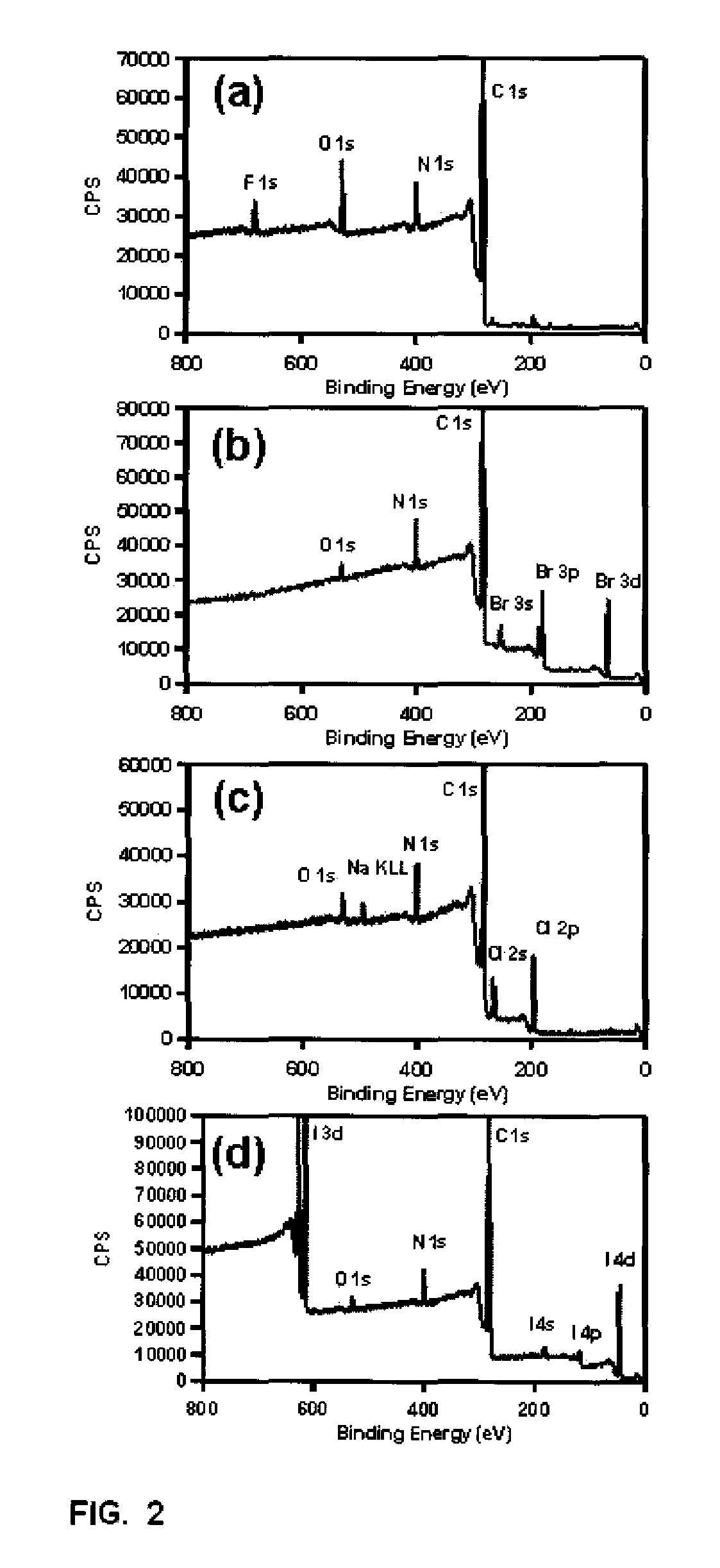
[0037]Spectra of XPS measurements of CPE powder samples are shown in FIG. 2 for PFN+F− (a), PFN+Cl− (b), PFN+Br− (c) and PFN+I− (d) samples. All spectra exhibited the corresponding halide anion signals with no evidence of any potassium signals indicating the removal of the excess salt added in the anion exchange procedure. The degree of anion exchange was determine to be greater than 97% in all samples by comparison to bromide signals, indicating successful anion exchange.

[0038]The absorption and PL spectra of CPEs films are shown in FIG. 3. The absorption and PL spectra of all the CPEs are similar with insignificant changes in band width and absorption (˜378 nm) and PL (˜428 nm) maxima. The PL spectra exhibit vibronic progression and no additional broad bands at longer wavelengths, indicating lack of π-π aggregates commonly observed in CPEs films due to processing in polar medium (16-20). The spectr...

example 3

Conclusions

[0047]In summary, a systematic investigation of the influence of the halide counter anion of CPE EILs on multilayer PLED device performance is presented. A general trend in device performance is observed with CPEs EILs containing halide counter anions (PFN+F−>PFN+Cl−>PFN+Br−>PFN+I−), which was determined to not correlate with difference in electron mobilities of the CPE, as has been observed in other CPE systems (9). Although not wishing to be bound by this idea, the device efficiency is believed to be influenced by the relative oxidation potential of the counter anion via oxidation by accumulated holes in the MEH-PPV / CPE interface. Measurements of the effects of reduced ion motion in PLED devices accomplished with pulse bias measurements results in a decrease in device efficiency with the relative more electrochemical stable PEN+F− system while and an increase in device efficiency with relatively less electrochemically stable PFN+Br− system. This correlates well with the...


PUM


Abstract

Counter anions having oxidative properties alter the performance of solution processed multilayer polymer light emitting diodes (PLEDs) that use cationic conjugated polyelectrolytes (CPEs) as electron injection layers (EILs). In some versions, PLEDs with poly(2-methoxy-5-(2′-ethylhexyloxy)-1,4-phenylene vinylene) (MEH-PPV) emissive layers and cationic CPE EILs are altered with halide counter anions to exhibit a systematic increase in device performance. Exemplary oxidative counter anions are halide counter anions with F−>Cl−>Br−>I− in terms of device performance.

Description

CROSS-REFERENCE TO RELATED APPLICATIONS[0001]This application claims the benefit of Provisional Patent Application No. 61 / 107,231, filed on Oct. 21, 2008, which is incorporated by reference herein.BACKGROUND[0002]1. Field of Invention[0003]This invention relates to cationic conjugated polyelectrolyte electron injection layers.[0004]2. Related Art[0005]Charge injection and transport play an important role in organic light emitting diodes (OLEDs) (1,2). In OLEDs, holes are injected from the anode into the highest occupied molecular orbital (HOMO) of the organic semiconductor. Similarly, electrons flow from the cathode to the lowest unoccupied molecular orbital (LUMO). A balance of injection and transport of both charge carriers is needed to increase the probability of hole / electron recombination, and hence, improve the light output at a given current density. In the absence of interfacial effects one needs to match the energies of the HOMO and the LUMO with the work function of the an...

Claims


Application Information

Patent Timeline
IPC IPC(8): H01L33/00H01L21/28H01L51/54
CPCH01L2251/552H01L51/5088H10K50/171H10K50/17H10K2101/30
Inventor NGUYEN, THUC-QUYENGARCIA, ANDRESBRZEZINSKI, JACEK
Owner RGT UNIV OF CALIFORNIA
Learn More