Catalytic materials, electrodes, and systems for water electrolysis and other electrochemical techniques

a technology of electrochemical techniques and catalysts, applied in the field of catalyst materials, can solve the problems of limiting the conversion efficiency, reducing the efficiency of anodic water oxidation, and requiring a large amount of effort, so as to reduce the cost of production, increase the rate of chemical electrolysis, and reduce the use of electrodes

Inactive Publication Date: 2010-04-29
SUN CATALYTIX CORP +1
View PDF81 Cites 58 Cited by
  • Summary
  • Abstract
  • Description
  • Claims
  • Application Information

AI Technical Summary

Benefits of technology

[0078]As noted, in some embodiments of the invention, catalytic materials and electrodes are provided which may produce oxygen gas and/or hydrogen gas from water. As shown in Equation 1, water may be split to form oxygen gas, electrons, and hydrogen ions. Although it need not be, an electrode and/or device may be operated in benign conditions (e.g., neutral or near-neutral pH, ambient temperature, ambient pressure, etc.). In some cases, the electrodes described herein operate catalytically. That is, an electrode may be able to catalytically produce oxygen gas from water, but the electrode might not necessarily participate in the related chemical reactions such that it is consumed to any appreciable degree. Those of ordinary skill in the art will understand the meaning of “catalytically” in this context. An electrode may also be used for the catalytic production of other gases and/or materials.
[0079]In some embodiments, an electrode of the present invention comprises a current collector and a catalytic material associated with the current collector. A “catalytic material” as used herein, means a material that is involved in and increases the rate of a chemical electrolysis reaction (or other electrochemical reaction) and which, itself, undergoes reaction as part of the electrolysis, but is largely unconsumed by the reaction itself, and may participate in multiple chemical transformations. A catalytic material may also be referred to as a catalyst and/or a catalyst composition. A catalytic material is not simply a bulk current collector material which provides and/or receives electrons from an electrolysis reaction, but a material which undergoes a change in chemical state of at least one ion during the catalytic process. For example, a catalytic material might involve a metal center which undergoes a change from one oxidation state to another during the catalytic process. Thus, catalytic material is given its ordinary meaning in the field in connection with this invention. As will be understood from other descriptions herein, a catalytic material of the invention that may be consumed in slight quantities during some uses and may be, in many embodiments, regenerated to its original chemical state.
[0080]In some embodiments, an electrode of the present invention comprising a current collector and a catalytic material associated with the current collector. A “current collector,” as used herein, is given two alternative definitions. In a typical arrangement of the invention, a catalytic material is associated with a current collector which is connected to an external circuit for application of voltage and/or current to the current collector, for receipt of power in the form of electrons produced by a power source, or the like. Those of ordinary skill in the art will understand the meaning of current collector in this context. More specifically, the current collector refers to the material between the catalytic material and the external circuit, through which electric current flows during a reaction of the invention or during formation of the electrode. Where a stack of materials are provided together including both an anode and a cathode, and one or more catalytic materials associated with the cathode and/or anode, where current collectors may be separated by membranes or other materials, the current collector of each electrode (e.g., anode and/or cathode) is that material through which current flows to or from the catalytic material and external circuitry connected to the current collector. In the case of a current collector thus far described, the current collector will typically be an object, separate from t

Problems solved by technology

Voltage in addition to E° that is required to attain a given catalytic activity, referred to as overpotential, limits the conversion efficiency and considerable effort has been expended by many researchers in efforts to reduce overpotential in this reaction.
Of

Method used


Image

  • Catalytic materials, electrodes, and systems for water electrolysis and other electrochemical techniques
  • Catalytic materials, electrodes, and systems for water electrolysis and other electrochemical techniques
  • Catalytic materials, electrodes, and systems for water electrolysis and other electrochemical techniques

Examples


example 1

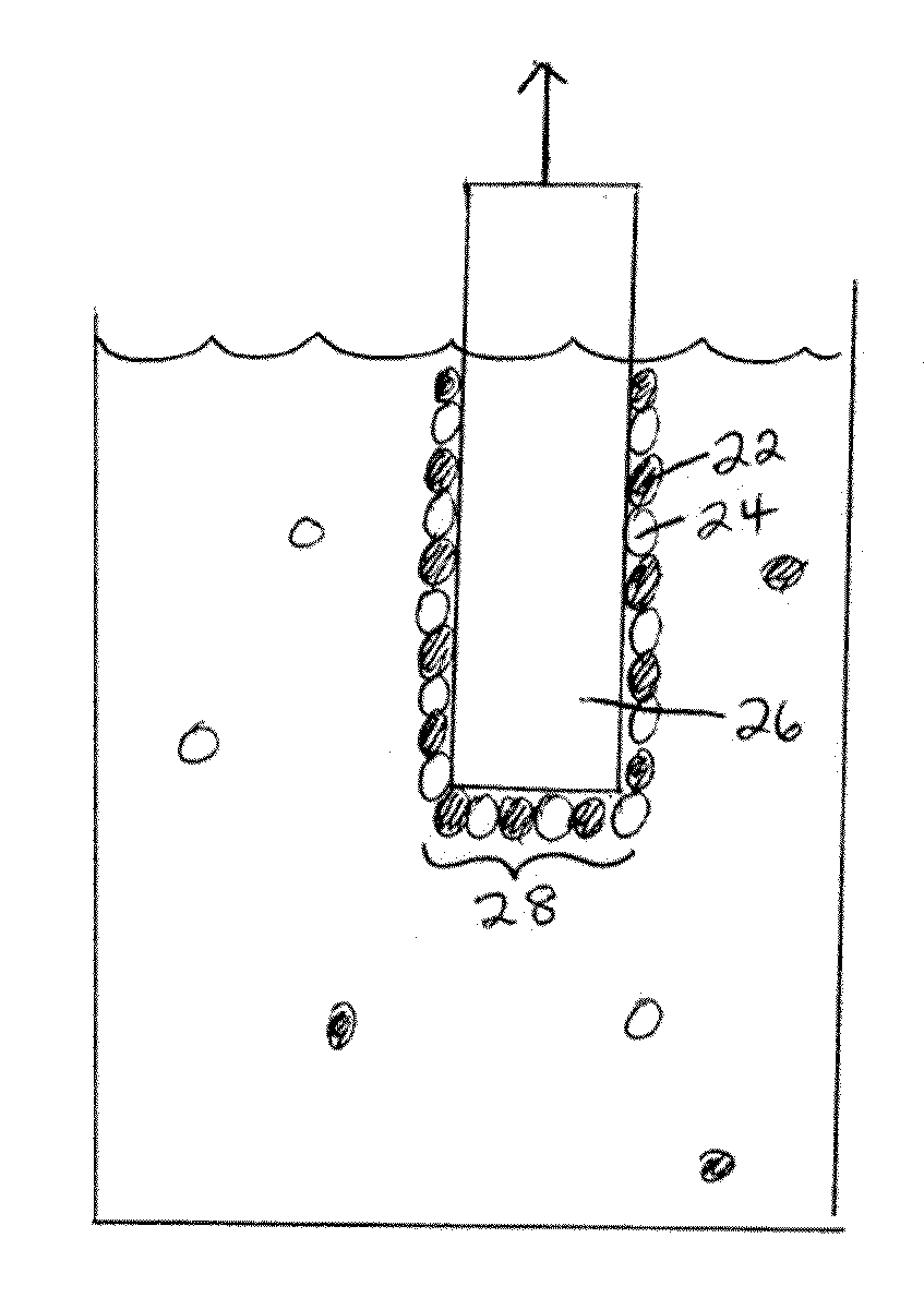
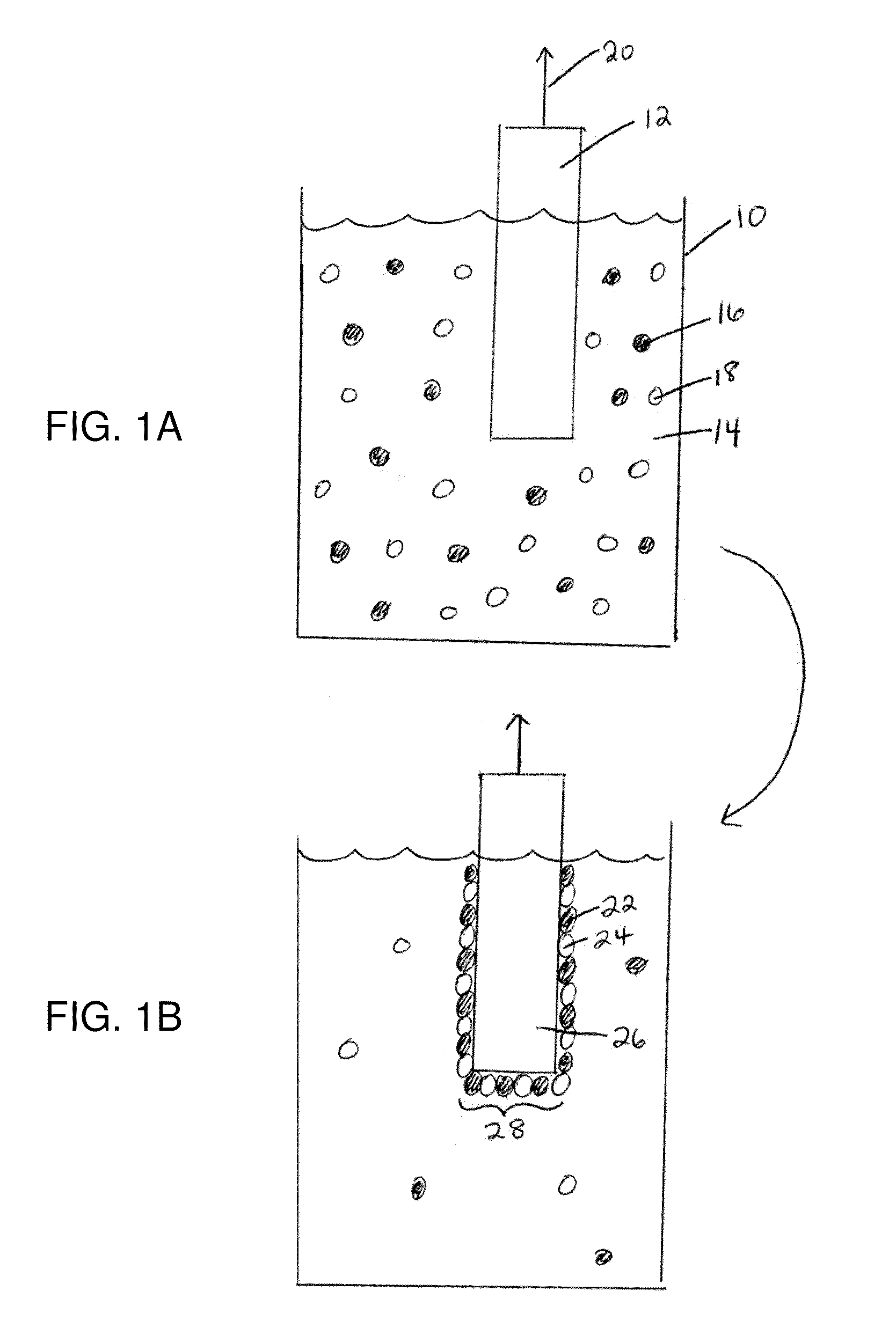
[0240]The following gives an example of the formation of an electrode according to a non-limiting embodiment. Cyclic voltammetry of a 0.5 mM solution of Co(NO3)2 in 0.1 M potassium phosphate pH 7.0 (herein referred to as neutral KPi electrolyte) exhibited an oxidation wave at 0.915 V followed by the onset of a strong catalytic wave at 1.0 V. As reported in this example, and those following, all voltages are reported relative to a normal hydrogen electrode, NHE, unless otherwise stated. A broad, relatively weak reduction wave was observed on the cathodic scan. FIG. 9A shows the cyclic voltammogram in neutral 0.1 M KPi electrolyte with (i) no Co2+ ion present and (ii) a scan with 0.5 mM Co2+ present. FIG. 9B shows a magnified version of the same graph in FIG. 9A.

example 2

[0241]This example relates to the preparation and characterization of a non-limiting example of an electrode according to a non-limiting embodiment. Indium-tin-oxide (ITO) was used as the current collector for bulk electrolysis to ensure a minimal background activity for O2 production. Application of 1.3 V to the current collector immersed (without stirring) in a 0.1 M potassium phosphate at pH 7.0 containing 0.5 mM Co2+, exhibited a rising current density that reached a peak value >1 mA / cm2 over 7-8 h. FIG. 9C shows the current density profile for bulk electrolysis at 1.3 V (vs. NHE) in neutral 0.1 M KPi containing 0.5 mM Co2+. During the time of the formation of the electrode, a dark coating formed on the ITO surface (e.g., the “catalytic material”) and effervescence from this coating became increasingly vigorous. The same result was observed using either CoSO4, Co(NO3)2, or Co(OTf)2 as the Co2+ source, indicating that the original Co2+ counterion and source could be exchanged. Th...

example 3

[0244]The following example describes the catalytic oxidation of water to form oxygen using an electrode according to a non-limiting embodiment, for example, the electrode describe in Example 2. The following example was performed in neutral KPi electrolyte in the absence of Co2+ using ˜1.3 cm2 of an electrode prepared according to Example 2. To confirm that water is the source of the O2 produced, an electrolysis was performed in helium-saturated buffer containing 14.5% 18OH2 in a gas tight electrochemical cell in line with a mass spectrometer. Helium carrier gas was continuously flowed through the headspace of the anodic compartment into the mass spectrometer and the relative abundances of 32O2, 34O2 and 36O2 were monitored at 2 second intervals. Within minutes of initiating electrolysis, the signals for the three isotopes rose above their background levels as the O2 produced by the catalyst escaped into the headspace. Upon terminating the electrolysis one hour later these signals ...


PUM

PropertyMeasurementUnit
Percent by massaaaaaaaaaa
Electric potential / voltageaaaaaaaaaa
Efficiencyaaaaaaaaaa

Abstract

Catalysts, electrodes, devices, kits, and systems for electrolysis which can be used for energy storage, particularly in the area of energy conversion, and/or production of oxygen, hydrogen, and/or oxygen and/or hydrogen containing species. Compositions and methods for forming electrodes and other devices are also provided.

Description

RELATED APPLICATIONS[0001]This application claims the benefit of U.S. Provisional Patent Application Ser. No. 61 / 073,701, filed Jun. 18, 2008, entitled “Catalyst Compositions and Electrodes for Photosynthesis Replication and Other Electrochemical Techniques,” by Nocera, et al., U.S. Provisional Patent Application Ser. No. 61 / 084,948, filed Jul. 30, 2008, entitled “Catalyst Compositions and Electrodes for Photosynthesis Replication and Other Electrochemical Techniques,” by Nocera, et al., U.S. Provisional Patent Application Ser. No. 61 / 103,879, filed Oct. 8, 2008, entitled “Catalyst Compositions and Electrodes for Photosynthesis Replication and Other Electrochemical Techniques,” by Nocera, et al., U.S. Provisional Patent Application Ser. No. 61 / 146,484, filed Jan. 22, 2009, entitled “Catalyst Compositions and Electrodes for Photosynthesis Replication and Other Electrochemical Techniques,” by Nocera, et al., and U.S. Provisional Patent Application Ser. No. 61 / 179,581, filed May 19, 20...

Claims


Application Information

Patent Timeline
IPC IPC(8): C02F1/469C25B11/06
CPCC25B1/04Y02E60/366C25B11/0442C25B11/04Y02W10/33Y02W10/37Y02E60/36C25B11/073Y02E60/50H01M4/90
Inventor NOCERA, DANIEL G.KANAN, MATTHEW W.SURENDRANATH, YOGESHDINCA, MIRCEALUTTERMAN, DANIEL A.REECE, STEVEN Y.ESSWEIN, ARTHUR J.
Owner SUN CATALYTIX CORP
Why Eureka
Try Eureka