Heat Stable Formed Ceramic, Apparatus And Method Of Using The Same

a ceramic and stable technology, applied in the field of ceramic components, methods, and thermal reactor apparatus, can solve the problems of high temperature reaction and process typically require more complex, specialized equipment, and high cost, and high temperature cracking process, etc., to achieve the effect of equipment, and reducing the cost of equipmen

Active Publication Date: 2010-05-27
EXXONMOBIL CHEM PAT INC
View PDF79 Cites 26 Cited by
  • Summary
  • Abstract
  • Description
  • Claims
  • Application Information

AI Technical Summary

Benefits of technology

[0020]In yet other embodiments, the invention includes a process for preparing a thermal reactor comprising the steps of: (a) preparing a ceramic component comprising bimodal, stabilized zirconia; and (b) sintering the ceramic component at a temperature of at least 1500° C.; (c) providing the sintered ceramic component in a reactive region of a thermal reactor; wherein after the sintering, the ceramic component reactive region compon...

Problems solved by technology

Higher temperature reactions and processes typically require more complex, costly, and specialized equipment to tolerate the intense heat and physical stress conditions, with equipment temperature, strength, and toughness limitations commonly defining upper limits for many of the processes and facilities.
Methane cracking processes, however, have been inefficient compared to other commercial processes for generation of acetylene and as compared to other cracking processes such as conventional steam cracking to produce olefins.
The high temperature processes (e.g., >1500° C.) have traditionally not scaled well and are generally only useful for relatively high-cost, specialty applications.
Processes such as thermally cracking methane to acetylene have largely been commercially unattractive due to thermal, chemical, and mechanical degradation of the reactor and related equipment.
In addition to physical temperature limitations for reactor materials, many prior art reactor materials that are inert at lower temperatures may become susceptible to chemistry alterations at high temperature, leading to premature equipment degradation and/or process interference, such as by generation of contaminants.
Although regenerative pyrolysis reactors are generally known in the art as capable of converting or cracking hydrocarbons, they have not achieved commercial or widespread use, due at least in part to the fact that they have not been successfully scaled well to a commercially economical size or commercially useful life span.
These drawbacks have resulted in use of compromised or alternative solutions, such as in the above example, commercial acetylene production is primarily accomplished via processing higher weight hydrocarbons such as ethane, propane, naphthas, and gas-oils at lower temperatures, such as by conventional steam crackers.
Further complicating the material stability and reliability issue has been exposure to large, cyclic temperature swings encountered during many pyrolysis processes.
Such temperature changes and product flow direction changes can impose severe physical strength and toughness demands upon the refractory materials at high temperature.
Material life expectancy at high temperature can be severely limited or precluded.
Such physical demands have also typically limited manufacturing and use of refractory materials to relatively simple shapes and components, such as bricks, tiles, spheres, and similar simple monoliths.
Reactor component functions and shapes have been limited for high severity services.
In some embodiments, however, the disclosed processes and apparatus may utilize relatively complex shaped refractory components, such as a thin-walled honeycomb monolith used to conduct process fluids through the reactor.
However, such materials have demonstrated insufficient strength, toughness, and/or chemical inertness, and are not amenable to use as certain desirable reactor components, such as for use as reactor fluid conduits, to facilitate large-scale commercialization.
Although some of the “Wulff” art disclose use of various refractory materials, a commercially useful process for methane cracking or other extreme high-temperature processes (e.g., >1500° C., >1600° C., and even >1700° C.) has not previously been achieved utilizing such materials.
The aforementioned practical obstacles have impeded large scale implementati...

Method used


Image

  • Heat Stable Formed Ceramic, Apparatus And Method Of Using The Same
  • Heat Stable Formed Ceramic, Apparatus And Method Of Using The Same
  • Heat Stable Formed Ceramic, Apparatus And Method Of Using The Same

Examples


example 1

ILLUSTRATIVE EXAMPLE 1

Close Packing of Bimodal Grains

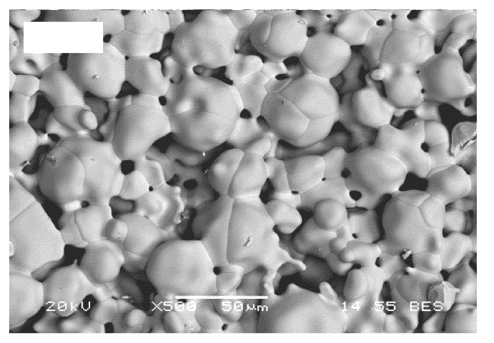
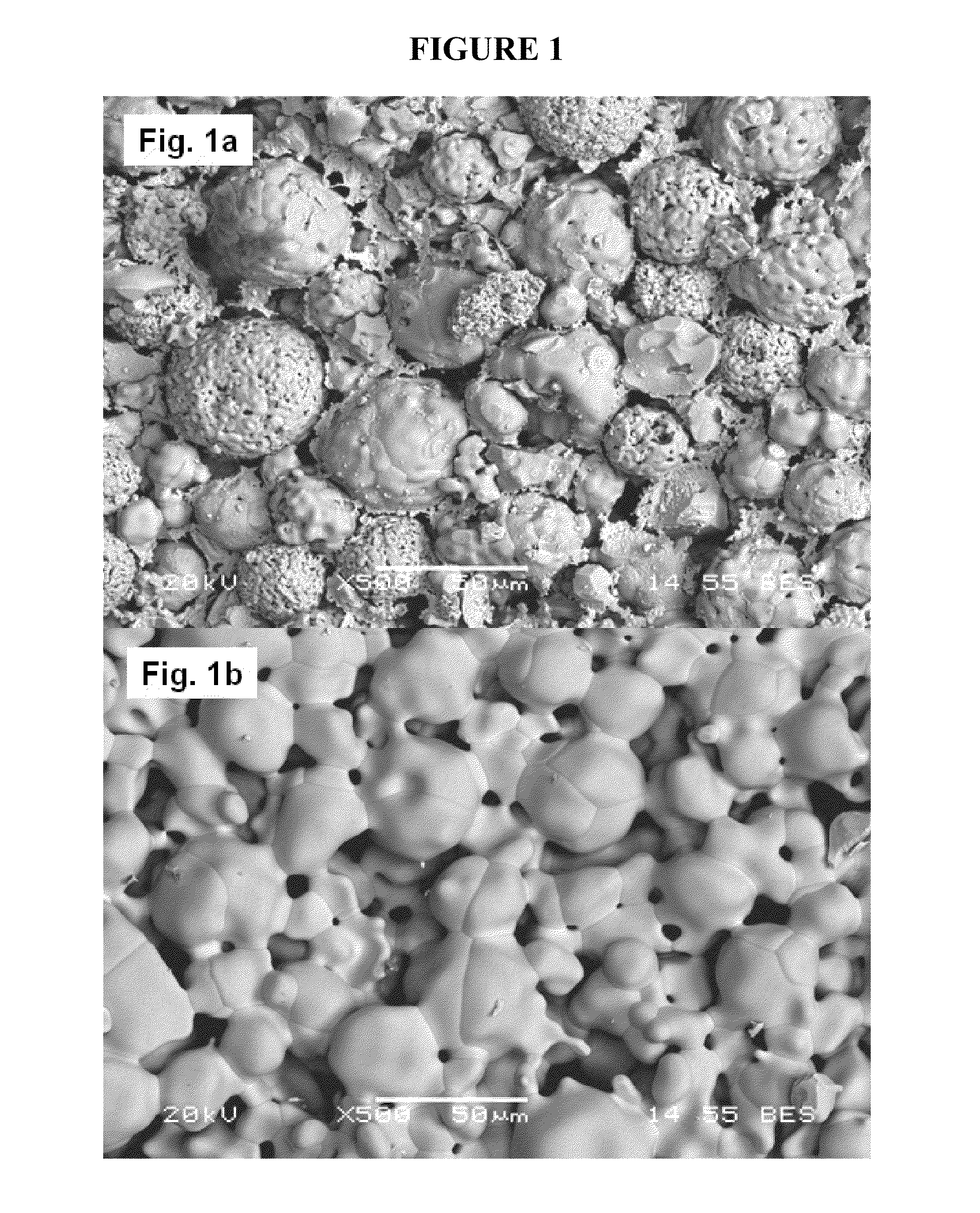
[0093]Table 4 depicts an exemplary multimodal grain distribution including a coarse grain mode of partially stabilized zirconia and a fine grain mode of more-stabilized zirconia, used for producing a stabilized zirconia matrix comprising a bimodal grain distribution. The coarse grit (H. C. Starck's Amperit® 827.054) is an agglomerated and sintered powder which is produced by spray drying of a suspension consisting of fine powders and organic binder and subsequent sintering. The fine grit (Tosoh TZ8Y) is produced by a hydrolysis process, which ensures uniform dispersion of yttria in zirconia and fine particle size.

TABLE 4CompanyGradeChemistry (wt %)SizeH.C.Amperit ®ZrO2: Balance, Y2O3: 7.0~9.0%,21~65 μmStarck827.054HfO2: 2.0%, Al2O3: 0.2%,(SphericalFe2O3: 0.3%, SiO2:Particle)0.5%, TiO2: 0.4%TosohTZ8YZrO2: Balance, Y2O3: 13.3%,0.05~2.0 μmAl2O3: 0.1%, Fe2O3: 0.01%,(CrystalliteSiO2: 0.02%, Na2O: 0.12%Size)

[0094]In the above example, 9...

example 3

ILLUSTRATIVE EXAMPLE 3

Close Packing with Multimodal Grain Distribution

[0117]The same coarse and fine grit materials of illustrative Example 1, that is, 90 vol % coarse grit of stabilized zirconia powder and 10 vol % of fine grit of stabilized zirconia powder, were mixed with organic binder for extrusion processing. The bimodal powder mixture was extruded to fabricate a green body in the size of about 0.55 mm thickness, 7.6 mm width, and 50 mm length. The extruded green body was dried and fired at 1500° C. for 2 hrs in an industrial kiln to fabricate a sintered body.

[0118]FIG. 3a of FIG. 3 illustrates an SEM image of the resulting sintered component (1500° C., 2 hrs) processed according to this example, wherein the legend bar represents 10 μm. In this image, substantially spherical coarse grits are in the D50 average grain size of about 30 μm and the D50 fine grits are in the average grain size of about 0.3 μm. The fine grits are beneficially distributed throughout the various pores ...


PUM

PropertyMeasurementUnit
Temperatureaaaaaaaaaa
Fractionaaaaaaaaaa

Abstract

In one aspect, the invention includes a heat stable, formed ceramic component that includes a multimodal grain distribution including (i) at least 50 wt % of coarse grains including stabilized zirconia, the coarse grains comprising a D50 grain size in the range of from 5 to 800 μm, based upon the total weight of the component; and (ii) at least 1 wt % of fine grains comprising a D50 average grain size not greater than one-fourth the D50 grain size of the coarse grain, dispersed within the coarse grains, based upon the total weight of the component; wherein after sintering, the component has porosity at ambient temperature in the range of from 5 to 45 vol. %, based on the formed volume of the component. In other embodiments, the invention includes a process for the manufacture of a hydrocarbon pyrolysis product from a hydrocarbon feed using a regenerative pyrolysis reactor system, comprising the steps of: (a) heating a pyrolysis reactor comprising a bi-modal stabilized zirconia ceramic component to a temperature of at least 1500° C. to create a heated reactive region, wherein after exposing the component to a temperature of at least 1500° C. for two hours the component has a bulk porosity measured at ambient temperature in the range of from 5 to 45 vol. %, based on the bulk volume of the component; (b) feeding a hydrocarbon feed to the heated pyrolysis reactor to pyrolyze the hydrocarbon feed and create a pyrolyzed hydrocarbon feed; and (c) quenching the pyrolyzed hydrocarbon feed to produce the hydrocarbon pyrolysis product.

Description

FIELD OF THE INVENTION[0001]This invention pertains to ceramic components, methods, and thermal reactor apparatus using the same, demonstrating improved physical and chemical stability in high temperature applications, facilitating improved process reliability and equipment durability. In some embodiments, the components may have particular utility in reactors such as may be used for thermally cracking or converting hydrocarbons, or for performing other high temperature chemical reactions. The invention includes refractory grade ceramic components that demonstrate improved strength, toughness, chemical stability, and thermal stability at high temperatures, such as above 1500° C., as compared to prior art refractory grade ceramics.BACKGROUND OF THE INVENTION[0002]Conventional steam crackers are a common tool for cracking volatile hydrocarbons, such as ethane, propane, naphtha, and gas oil. Similarly, other thermal or pyrolysis reactors, including reverse flow and other regenerative r...

Claims


Application Information

Patent Timeline
IPC IPC(8): C10G11/04C04B38/00
CPCC04B35/482C04B35/486C10G9/26C10G9/00C04B38/0006C04B2111/00793C04B2111/0081C04B2235/3201C04B2235/3206C04B2235/3208C04B2235/3217C04B2235/3224C04B2235/3225C04B2235/3227C04B2235/3229C04B2235/3232C04B2235/3239C04B2235/3241C04B2235/3246C04B2235/3251C04B2235/3256C04B2235/3258C04B2235/3262C04B2235/3272C04B2235/3275C04B2235/3279C04B2235/3418C04B2235/5436C04B2235/5445C04B2235/5472C04B2235/6021C04B2235/72C04B2235/77C04B2235/783C04B2235/785C04B2235/786C04B2235/788C04B2235/95C04B2235/96C04B38/0074
Inventor CHUN, CHANGMINHERSHKOWITZ, FRANK
Owner EXXONMOBIL CHEM PAT INC
Why Eureka
Try Eureka