Polyolefin microporous membrane

a polyolefin microporous membrane and polyolefin microporous membrane technology, applied in the field of microporous membranes, can solve the problems of deteriorating inability to provide inexpensive batteries, and difficulty in raising the capacity further by using, so as to improve the cycle performance of the battery, improve the oxidation resistance of the polyolefin microporous membrane, and improve the oxidation resistan

Inactive Publication Date: 2010-05-27
ASAHI KASEI CHEM CORP
View PDF18 Cites 46 Cited by
  • Summary
  • Abstract
  • Description
  • Claims
  • Application Information

AI Technical Summary

Benefits of technology

[0038]According to the polyolefin microporous membrane of the present invention, since protrusions contact with a positive electrode or a negative electrode, and it provides a space between the positive electrode and the negative electrode, the protrusions absorb a dimensional change of the negative electrode caused by its expansion in battery charging, thereby preventing compression or collapse of the polyolefin microporous membrane caused by expansion of the negative electrode at the space portion, resulting in improvement of the cycle performance of the battery. This effect is especially advantageous when the negative electrode is alloy-based, and it is also advantageous when the negative electrode is carbon-based. The presence of the above-mentioned space improves: the impregnation with an electrolyte, injection with an electrolyte, and retention of an electrolyte. This effect is more advantageous when the spacing between stacked electrode plates of the battery is small or a winding pressure of a wound electrode plate is high. In addition, due to the presence of the above-mentioned space, oxidation resistance of the polyolefin microporous membrane is also improved. This effect is more advantageous when the positive electrode active material has high oxidation property or a charging voltage is high. Further, the pore structure of the separator surface is densified by embossing, resulting in improvement in mechanical properties such as puncture strength and tensile strength. This effect is more advantageous when the separator is thin.
[0039]The production method of a polyolefin microporous membrane according to the present invention enables to produce a polyolefin microporous membrane suited for separator for battery as described above without collapsing the microporous structure or causing pinholes.

Problems solved by technology

As a negative electrode material of lithium ion batteries, carbon materials such as non-graphitizable carbon and graphite have conventionally been employed, but effective capacity of these carbon materials has already reached saturation from the standpoint of industrial technology and it is difficult to raise the capacity further by using them.
Use of a metal such as silicon or tin, or a semi-metal for a negative electrode however deteriorates the cycle performance of the battery in an early stage because a volume change of the battery due to charging / discharging, in other words, an expansion factor or shrinkage factor is larger than that of carbon materials.
This method however needs a new step for this application so that it cannot provide inexpensive batteries.
This method however does not succeed in sufficient improvement in the cycle performance.
When the microporous membranes described in these documents are used as a separator of lithium ion batteries, however, they may cause problems such as deterioration in battery capacity and generation of internal short-circuit failure.
Thus, polyolefin microporous membranes capable of realizing good battery properties when used as a separator for batteries, in particular, as a separator for batteries using an alloy negative electrode have not yet been available.

Method used


Image

  • Polyolefin microporous membrane
  • Polyolefin microporous membrane

Examples


example 1

[0136]In a tumbler blender, 95 wt. % of a polyethylene homopolymer having Mv of 250000 and 5 wt. % of a polypropylene homopolymer having Mv of 400000 were dry blended. To 99 wt. % of the pure polymer mixture thus obtained was added 1 wt. % of pentaerythrityl-tetrakis-[3-(3,5-di-t-butyl-4-hydroxyphenyl)propionate] as an antioxidant, followed by dry-blending in the tumbler blender again to obtain a polymer-containing mixture. After the atmosphere was substituted with nitrogen, the polymer-containing mixture thus obtained was supplied to a twin-screw extruder in a nitrogen atmosphere by using a feeder. Liquid paraffin (having a viscoelasticity of 7.59×10⁻⁵ m2 / s at 37.78° C.) was injected into the cylinder of the extruder via a plunger pump. The first peak available at 10° C. / min by the DSC method, that is, a melting point of the pure polymer mixture, was 137.2° C.

[0137]The feeder and the pump were adjusted so that a liquid paraffin amount ratio in the total mixture to be extruded after...

example 2

[0144]In a tumbler blender, 47.5 wt. % of a polyethylene homopolymer having Mv of 700000, 47.5 wt. % of a polyethylene homopolymer having Mv of 250000, and 5 wt. % of a polypropylene homopolymer having Mv of 400000 were dry blended. To 99 wt. % of the pure polymer mixture thus obtained was added 1 wt. % of pentaerythrityl-tetrakis-[3-(3,5-di-t-butyl-4-hydroxyphenyl)propionate] as an antioxidant, followed by dry blending in the tumbler blender again to obtain a polymer-containing mixture. After the atmosphere was substituted with nitrogen, the obtained polymer-containing mixture was supplied to a twin-screw extruder in a nitrogen atmosphere by using a feeder. Liquid paraffin (having a viscoelasticity of 7.59×10⁻⁵ m2 / s at 37.78° C.) was injected into the cylinder of the extruder via a plunger pump.

[0145]The feeder and the pump were adjusted so that a liquid paraffin amount ratio in the total mixture to be extruded after melting and kneading became 65 wt. %. The melting and kneading we...

example 3

[0152]In the same manner as in Example 2 except that after the kneaded melt was extruded onto a cooling roll, the extrudate was cast by bank formation method, embossing was carried out under the following conditions, a biaxial orientation temperature was 118° C. and a thermal fixing temperature was 122° C. a polyolefin microporous membrane was prepared.

[0153]In the present example, the gel sheet was passed between two embossing rolls (roll 1 and roll 2) while adjusting a linear pressure between the rolls to 110 N / mm. The roll 1 and the roll 2 had each an outer diameter of 100 mm and an embossed pattern of diagonal lattices with a density of 64 meshes / inch and a depth of 0.102 mm. Their surface temperature was adjusted to 85° C.

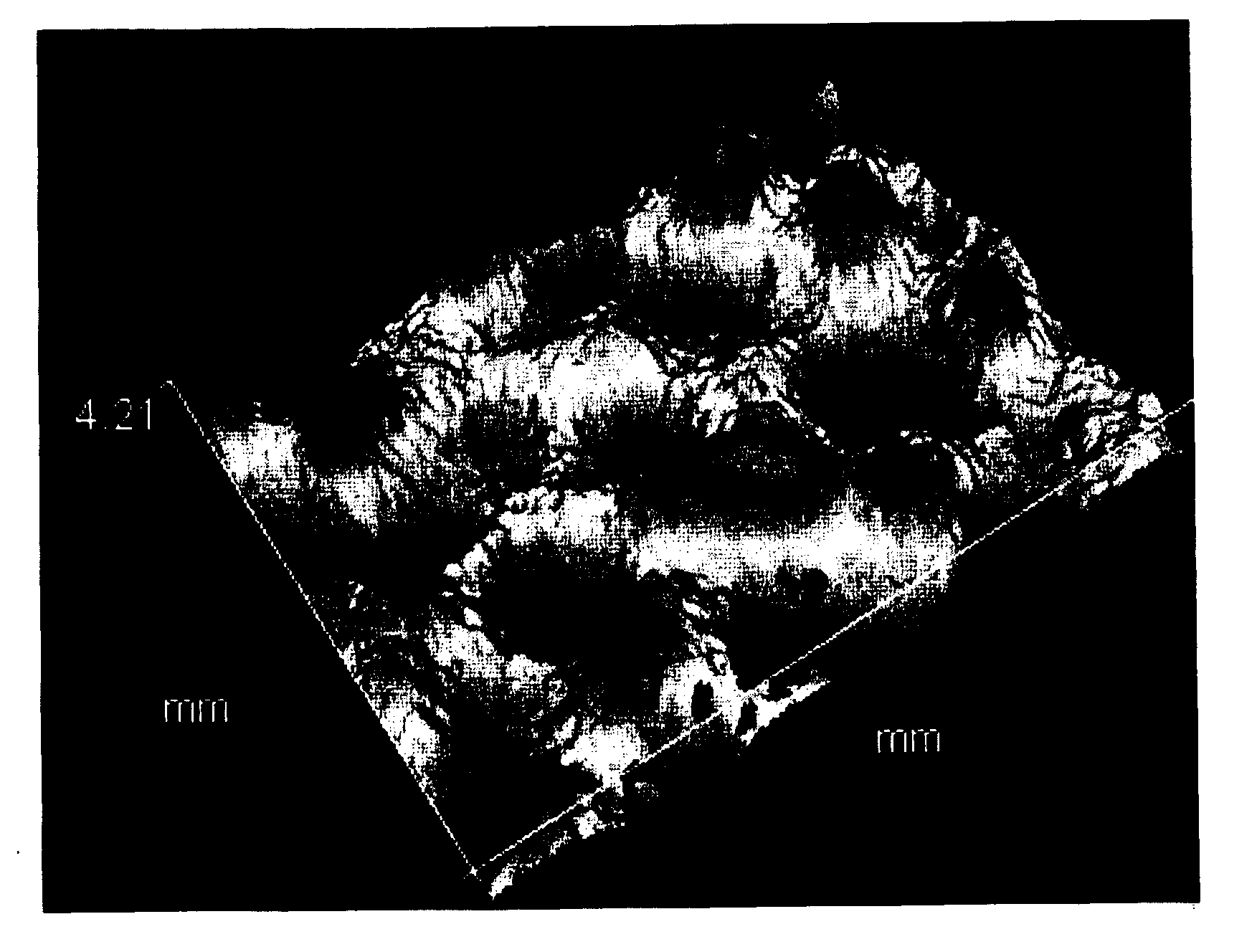
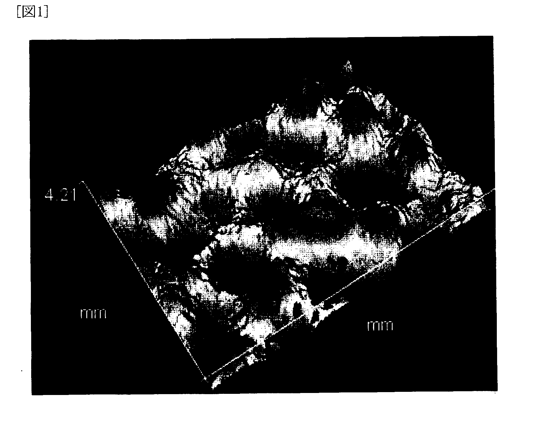
[0154]With regard to the polyolefin microporous membrane thus obtained, various physical properties, battery performance, and electrolyte retention condition were evaluated and the evaluation results are shown in Table 1, while observation results of the shape...


PUM

PropertyMeasurementUnit
heightaaaaaaaaaa
pore diameteraaaaaaaaaa
thicknessaaaaaaaaaa

Abstract

Provided are a polyolefin microporous membrane having a thickness of from 1 to 100 μm, a pore diameter of from 0.01 to 1 μm, and protrusions having a height of from 0.5 to 30 μm formed by embossing on at least one of the surfaces of the membrane; a production method of the membrane; and a separator for battery made of the membrane.

Description

TECHNICAL FIELD[0001]The present invention relates to a microporous membrane widely used as a separation membrane for separation or selective transmission of a substance or as a separator material of an electrochemical reaction apparatus such as alkaline battery, lithium ion battery, fuel cell, or capacitor. In particular, the invention pertains to a polyolefin microporous membrane suited for use as a separator for nonaqueous electrolyte battery.BACKGROUND ART[0002]Polyolefin microporous membranes have been used for various purposes as a separation membrane for separation or selective transmission of various substances or a separator material. Examples of their usage include microfiltration membrane, separator for fuel cell or capacitor, base material of a functional membrane for causing a functional material to fill in pores of the base material and thereby causing the emergence of its new function, and a separator for battery. Above all, polyolefin microporous membranes are especi...

Claims


Application Information

Patent Timeline
Patent Type & Authority Applications(United States)
IPC IPC(8): H01M2/18H01M2/16B29C47/00H01M10/0565H01M50/417H01M50/463H01M50/489H01M50/491H01M50/494
CPCH01M2/1653H01M2300/0082H01M10/0565H01M2/18Y02E60/10H01M50/463H01M50/417H01M50/491H01M50/494H01M50/489C08J9/22C08J5/22H01M10/052H01M50/411H01M50/406
Inventor SAKO, KENTARONISHIMURA, YOSHIFUMI
Owner ASAHI KASEI CHEM CORP
Why Eureka
Try Eureka