
Separator and non-aqueous electrolyte secondary battery

a secondary battery and electrolyte technology, applied in the field of non-aqueous electrolyte secondary batteries, can solve the problems of reducing battery performance and prone to crushing of separators, and achieve the effects of favorable cycle performance, high correlation between the dynamic hardness of the separator and the cycle performan

Active Publication Date: 2010-06-17
PANASONIC CORP
View PDF15 Cites 19 Cited by
  • Summary
  • Abstract
  • Description
  • Claims
  • Application Information

AI Technical Summary

Benefits of technology

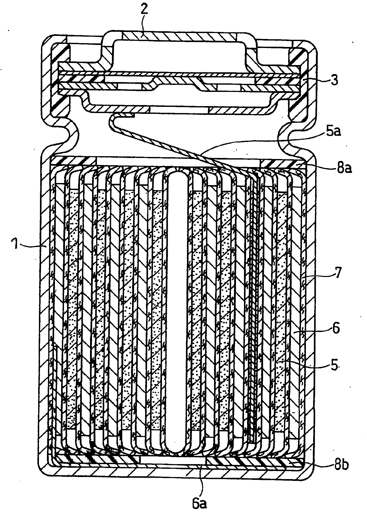
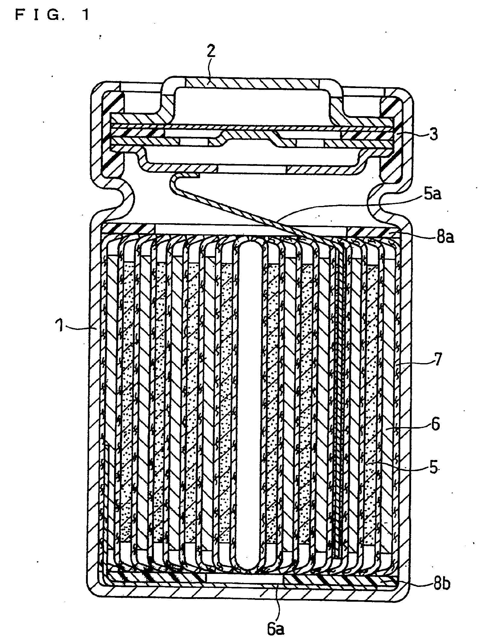
[0023]The dynamic hardness of the separator is highly correlated to the cycle performance. When the dynamic hardness DH obtained when the load to an indenter reaches 12 kgf / cm2 satisfies 1000≦DH, a non-aqueous electrolyte secondary battery with favorable cycle performance can be obtained. The non-aqueous electrolyte impregnated into a separator having a dynamic hardness of 1000 or more is not easily pressed out of the separator even when the battery internal pressure is elevated in association with the expansion of the electrode or the generation of gas. Consequently, the migration of lithium ions is ensured and the increase in the battery resistance is suppressed.
[0024]In the case where the separator has the porous layer X including a polyolefin and the porosity of the porous layer X is 35% or more and 65% or less, the voids in the separator is suitable for migration of lithium ions. As such, the electric characteristics of the separator become particularly favorable. In the case where in a pore size distribution of the porous layer X measured with a mercury porosimeter, the ratio of pores having a pore size of 0.02 μm or more and 0.2 μm or less is 40 vol % or more relative to a total pore volume, since a large number of pores having a small pore size exist, the separator becomes homogeneous. As such, the separator has an appropriate elasticity and a high strength.
[0025]In the case where the separator has the porous layer Y including a heat resistant resin, and a thermal deformation temperature (deflection temperature under load) of the heat resistant resin is 160° C. or more, it is more unlikely that the separator is compressed or deformed. Moreover, in a high temperature test of the battery also, the presence of the heat resistant resin makes it possible to achieve a high level of safety.
[0026]According to the present invention, a non-aqueous electrolyte secondary battery excellent in cycle performance can be provided.

Problems solved by technology

One of the causes of the reduction in battery performance is in an expansion phenomenon of the negative electrode.
In other words, the separator tends to be easily crushed when the battery internal pressure is elevated.

Method used


Image

  • Separator and non-aqueous electrolyte secondary battery
  • Separator and non-aqueous electrolyte secondary battery

Examples


example 1

(a) Fabrication of Positive Electrode

[0072]A positive electrode material mixture paste was prepared by stirring, with a double arm kneader, 3 kg of lithium cobaltate serving as a positive electrode active material, 1 kg of “#1320 (trade name)” available from KUREHA CORPORATION (an NMP solution containing 12 wt % of PVDF) serving as a positive electrode binder, 90 g of acetylene black serving as a conductive agent, and an appropriate amount of NMP. The positive electrode material mixture paste was applied onto both faces of a 15-μm-thick band-shaped positive electrode current collector made of an aluminum foil, except for a connecting portion for a positive electrode lead. The applied positive electrode material mixture paste was dried, and rolled with rollers to form a positive electrode material mixture layer. The density of the active material layer in the positive electrode material mixture layer (weight of active material / volume of material mixture layer) was 3.3 g / cm3. The tota...

example 2

[0103]A PO separator (lot No. 2) was fabricated in the same manner as in Example 1 except that a resin composite obtained by mixing 30 parts by weight of high density polyethylene, 20 parts by weight of low density polyethylene, and 50 parts by weight of dioctyl phthalate was used, and the stretching rate was set to 3.3 times. A cylindrical battery was fabricated in the same manner as in Example 1 except that the separator of lot No. 2 was used, and evaluated in the same manner. The thickness of the separator of lot No. 2 was 23 μm.

example 3

[0104]A PO separator (lot No. 3) was fabricated in the same manner as in Example 1 except that a resin composite obtained by mixing 30 parts by weight of high density polyethylene, 15 parts by weight of low density polyethylene, and 55 parts by weight of dioctyl phthalate was used, and the stretching rate was set to 2.9 times. A cylindrical battery was fabricated in the same manner as in Example 1 except that the separator of lot No. 3 was used, and evaluated in the same manner. The thickness of the separator of lot No. 3 was 24 μm.


PUM

PropertyMeasurementUnit
porosityaaaaaaaaaa
porosityaaaaaaaaaa
pore sizeaaaaaaaaaa

Abstract

In a non-aqueous electrolyte secondary battery, a separator in which its dynamic hardness DH obtained when the load to an indenter reaches 12 kgf / cm2 is 1000 or more is used. This separator includes at least one porous layer X including a polyolefin, and at least one porous layer Y including a heat resistant resin. The porosity of the porous layer X is 35% or more and 65% or less. In a pore size distribution of the porous layer X measured with a mercury porosimeter, a ratio of pores having a pore size of 0.02 μm or more and 0.2 μm or less is 40 vol % or more relative to a total pore volume. The thermal deformation temperature of the heat resistant resin is 160° C. or more.

Description

TECHNICAL FIELD[0001]The present invention mainly relates to an improvement of a separator for use in non-aqueous electrolyte secondary batteries. The separator of the present invention provides a non-aqueous electrolyte secondary battery excellent in cycle performance.BACKGROUND ART[0002]In recent years, there has been a rapid advancement in the development of portable and cordless electronic equipment for consumers. Accordingly, demand is growing for small-size and light-weight secondary batteries with higher energy density to serve as a power source for driving such electric equipment. In particular, non-aqueous electrolyte secondary batteries (e.g., lithium ion secondary batteries), because of their high voltage and high energy density, are expected to grow significantly in the future as a power source for notebook personal computers, cell phones, AV equipment, and the like. Nickel-cadmium storage batteries or nickel-metal hydride storage batteries including an alkaline aqueous ...

Claims


Application Information

Patent Timeline
Patent Type & Authority Applications(United States)
IPC IPC(8): H01M4/00H01M2/16H01M4/38H01M4/48H01M4/485H01M4/50H01M4/505H01M4/52H01M4/525H01M10/05H01M10/052H01M10/36H01M50/414H01M50/449H01M50/489H01M50/491
CPCH01M2/1653H01M10/05H01M2/1686Y02E60/10H01M50/449H01M50/491H01M50/414H01M50/489H01M10/02H01M4/48H01M50/417H01M2300/0017H01M2004/028H01M2004/027
Inventor KASAMATSU, SHINJIOKAMURA, KAZUHIRO
Owner PANASONIC CORP
Learn More