Economic solar electricity panel system

a solar energy panel and solar energy technology, applied in the direction of lighting and heating equipment, pv power plants, sustainable buildings, etc., can solve the problems of reduced sun energy, uneconomic collection, and weight limitation, and achieve the effect of preventing contamination, reducing cost and wind resistance, and light weigh

Inactive Publication Date: 2010-07-01
COOL PLANETABOLAR
View PDF10 Cites 5 Cited by
  • Summary
  • Abstract
  • Description
  • Claims
  • Application Information

AI Technical Summary

Benefits of technology

[0009]Since the sun moves across the sky relatively slowly each day, the controller to move the heat conductive panel may be small, light weight, inexpensive and reliable. Typically, a small dither built into the controller and a monitor of electrical output, or a computer with a clock can be used to keep the heat conductive panel in the proper position throughout the day. Being small and driving a light weight panel, the controller can be solar powered from a small fixed solar cell on the solar panel, sized to produce enough electrical power to operate the controller when the sun is beyond the 30° from mid-afternoon, or a rechargeable battery charged during the preceding day. Since the morning “start” and afternoon “stop” positions of the heat conductive panel are the same, the controller is required to move the heat conductive panel only when sufficient solar should exist. By mounting the heat conductive panel by at least three pins in at least three mated arculate grooves, the heat conductive panel can be maintained parallel to the lens and in proper position so that the plurality of lines of solar energy produced by the lenses remain on the plurality of photovoltaic strips. The controller may be a single chip computer with a look up table memory or an equation of the sun's movement for the installation position for time and position synchronism.
[0010]The lenses are made from acrylic plastic that is extruded, or extruded with calendar rolls, embossing drums or other shape controlling processes and then cut to the proper length. Optically, the lenses in the lens array meet the system optical tolerance requirements, such as focal length and pitch at an economic system cost. Other lens array fabrication methods such as casting, injection molding, and polishing are generally too expensive for consideration. The arculate path of the heat conductive base allows some compromise in line width about the theoretical focus depth so that solar energy is collected most economically. The heat conductive panel is environmentally sealed within the case of the solar panel by a flexible bladder to prevent contamination by insects, dust, or moisture in the volume between the array of lenses and the heat conductive base. The flexible bladder may be molded with accordion folds to reduce the stresses therein and provide a reasonable lifetime even though the bladder may be subject to damage due to temperature and wind thrown debris. Therefore, removable mounting for the bladder is preferred so it can easily be replaced.
[0011]It is therefore a principle object of the present invention to provide efficient stationary solar panels at an economic cost.
[0012]Another object is to concentrate solar energy to minimize the amount of photovoltaic material required to convert the solar energy falling on a given area into electricity.
[0013]Another object is to minimize the space required, especially for solar module depth profile, and weight for a solar array.
[0014]Another object is to provide solar panels that maximize the use of available roof space for the production of electricity while minimizing the need to modify the roof of a commercial building for “after market” installation.

Problems solved by technology

The lens array is aligned perpendicular to the horizon, such results in a larger acceptance angle requirement so usually, the lens are aligned parallel to the horizon to collect sunlight over a wide arc of solar movement and to concentrate the collected light onto relatively expensive narrow strips of photovoltaic material positioned beneath and parallel thereto.
A concentration ratio of 20 to 1 for sunlight onto the photovoltaic strips is typical, the ratio required being a function of photovoltaic material cost to lens cost with the high ratios being limited by the heat buildup in the photovoltaic material, aberrations at extreme off axis collection, mechanical alignment tolerance costs, and panel profile height limitations of weight, cost and wind resistance.
Usually the sun's energy is diminished by the atmosphere and angle when positioned beyond 60° from high noon and becomes uneconomic to collect.

Method used


Image

  • Economic solar electricity panel system
  • Economic solar electricity panel system
  • Economic solar electricity panel system

Examples


Embodiment Construction

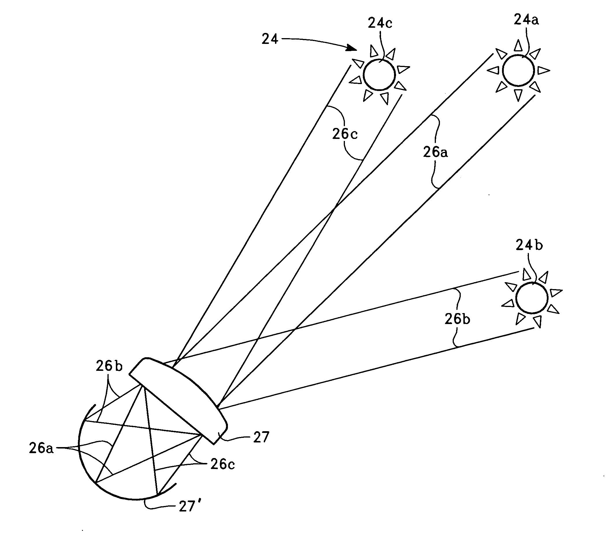
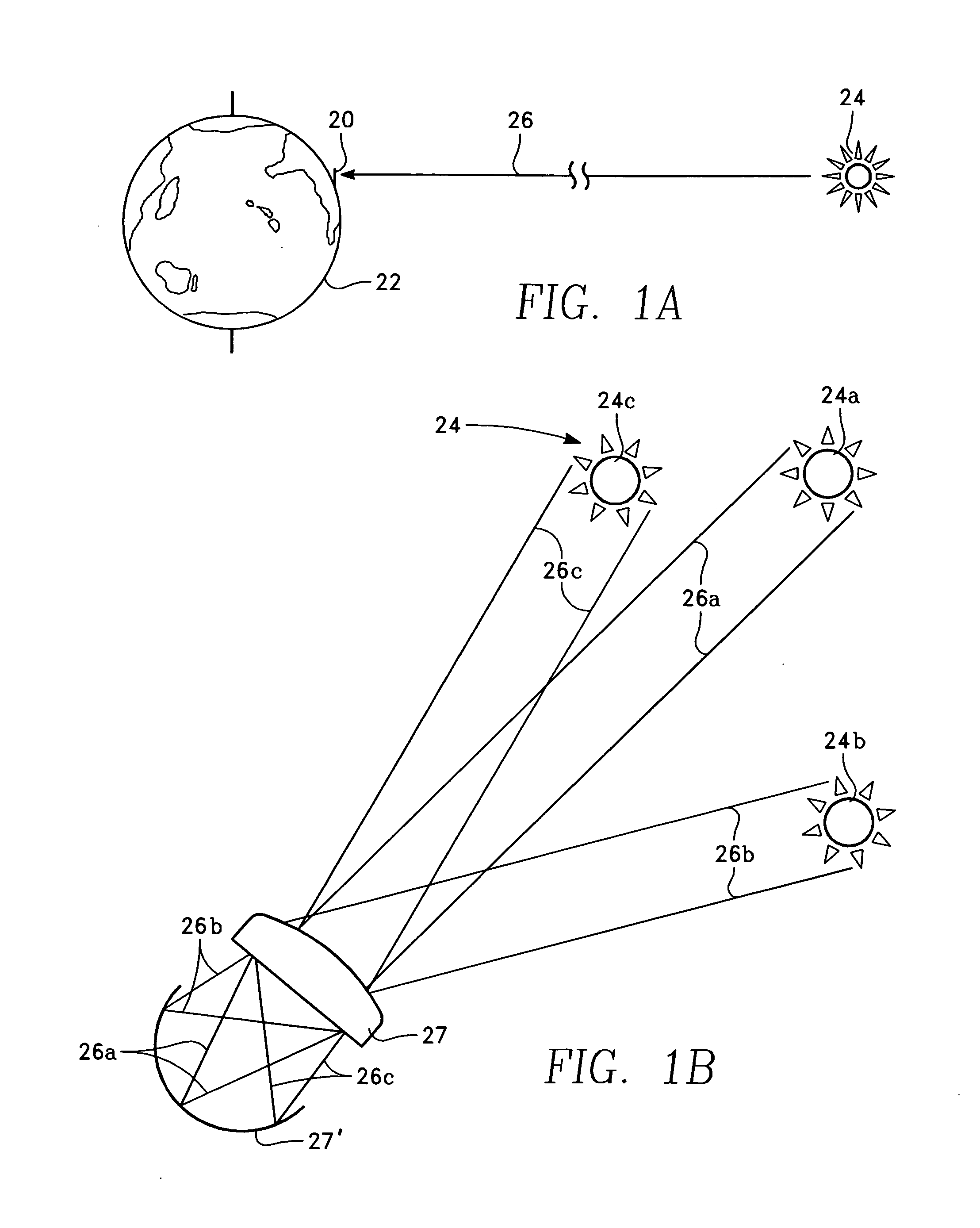
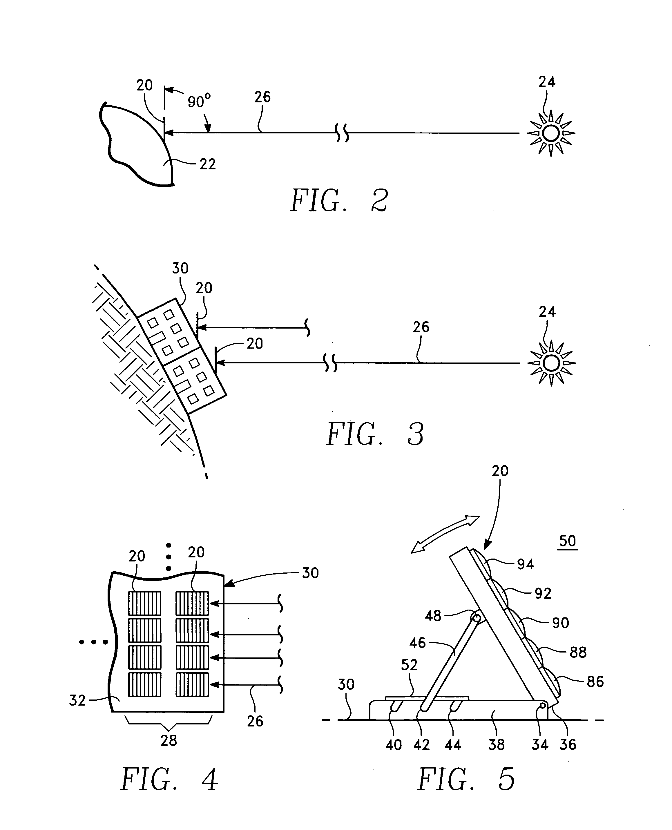
[0035]Referring to the drawings more particularly by reference numbers, number 20 in FIGS. 1A and 2 refers to a solar panel constructed according to the present invention in position on the earth 22 with respect to the sun 24. As shown in FIGS. 1A, 1B, and 2, the panel 20 is normally positioned at an angle to the earth 22 approximating the latitude of the panel's location on the earth 22. In most cases, the panel 20 is positioned perpendicular to the sun's rays 26a at mid-morning and mid-afternoon (sun 24a position) so that the sun's rays 26b and 26c strike the lens 27 (the lens 27 extends into the paper) at an acceptance angle of 30° to 35° close to sunrise and sunset (sun position 24b), and at high noon (sun position 24c). However, solar electricity is normally a “topping” electrical source, to supply electricity during peak demands. If the peak demand is caused by air conditioning, ambient air temperature lags the sun 24 by about two hours, so the panel 20 may be orientated to be...


PUM


Abstract

Economical sunlight collection panels are constructed to minimize the cost to generate electricity from solar radiation. The panels use a plurality of fixed plastic linear lenses to collect sunlight over a wide arc of solar movement and concentrate the collected light onto a plurality of relatively expensive narrow strips of photovoltaic material. The photovoltaic strips are moved in an arculate path and maintained parallel to the lenses so that the lines of light concentrated by the lens remain on the strips and produce electricity over a wide portion of the sun's path across the sky, even though the area of the photovoltaic strips is minimized for economy.

Description

BACKGROUND OF THE INVENTION[0001]1. Technical Field of the Invention[0002]The present invention relates to an economical sunlight concentration apparatus for gathering sunlight and concentrating it to shine on a plurality of narrow strips of photovoltaic material.[0003]2. Related Art[0004]In recent years, various types of sunlight collection apparatuses for gathering sunlight, i.e. natural light, and guiding the light to shine on photovoltaic material have been proposed. Some involve fiber optics, electro-optic lens, or large motion bases. For any of such systems to be commercially viable, they must maximize the usage of available space and minimize the cost of generated electricity by substituting economical apparatus for expensive apparatus and by maximizing the usage of available space. In most cases, photovoltaic material is the most expensive component of solar electric energy systems so its usage must be minimized. Also expensive tracking systems are not viable, and glass, or ...

Claims


Application Information

Patent Timeline
Patent Type & Authority Applications(United States)
IPC IPC(8): H01L31/052H01L31/00H01L31/042F24S23/30
CPCH01L31/048H01L31/052Y02B10/12Y02B10/14Y02E10/52H01L31/0543H01L31/0547Y02B10/10
Inventor PALEN, EDWARDFULTON, MICHAEL LEENEWELL, MICHAEL PHILLIPBROWN, RICHARD
Owner COOL PLANETABOLAR
Why Eureka
Try Eureka