Charged particle analyser and method

a particle analysis and charge technology, applied in the direction of particle separator tubes, instruments, electrical equipment, etc., can solve the problems of difficult identification of thin layers and features below 1000 nm in dimension, limited range of low energy electrons, and rare in conventional sems, etc., to achieve easy retraction, low loss, and high acceptance angle

Active Publication Date: 2010-07-01
OXFORD INSTR NANOTECH TOOLS
View PDF17 Cites 23 Cited by
  • Summary
  • Abstract
  • Description
  • Claims
  • Application Information

AI Technical Summary

Benefits of technology

[0038]The invention thus provides a compact charged particle, analyser that has a high acceptance angle and is capable of selecting low loss particles or measuring the particle energy spectrum. The analyser can be arranged to be easily retracted when not in use and is therefore compatible with conventional SEMs where there are often several typ...

Problems solved by technology

This can make the identification of thin layers and features below 1000 nm in dimension difficult.
Low energy electrons have a very limited range and only escape from layers very close to the surface where the probe is still narrow.
While Auger spectrometry is commonly available on Ultra High Vacuum (UHV) “surface analysis” microscopes (typically 10−9 torr), it is rarely available in conventional SEMs (−5 torr) partly because of the size and expense of high resolution electron spectrometers.
However, it is not always possible to tilt the sample sufficiently and spatial resolution and depth of field is compromised in this configuration.
Spherical grid retarding analysers occupy a large volume around the sample, require a fixed sample/analyser position and the presence of even small stray magnetic fields degrades the energy resolution considerably....

Method used


Image

  • Charged particle analyser and method
  • Charged particle analyser and method
  • Charged particle analyser and method

Examples


Embodiment Construction

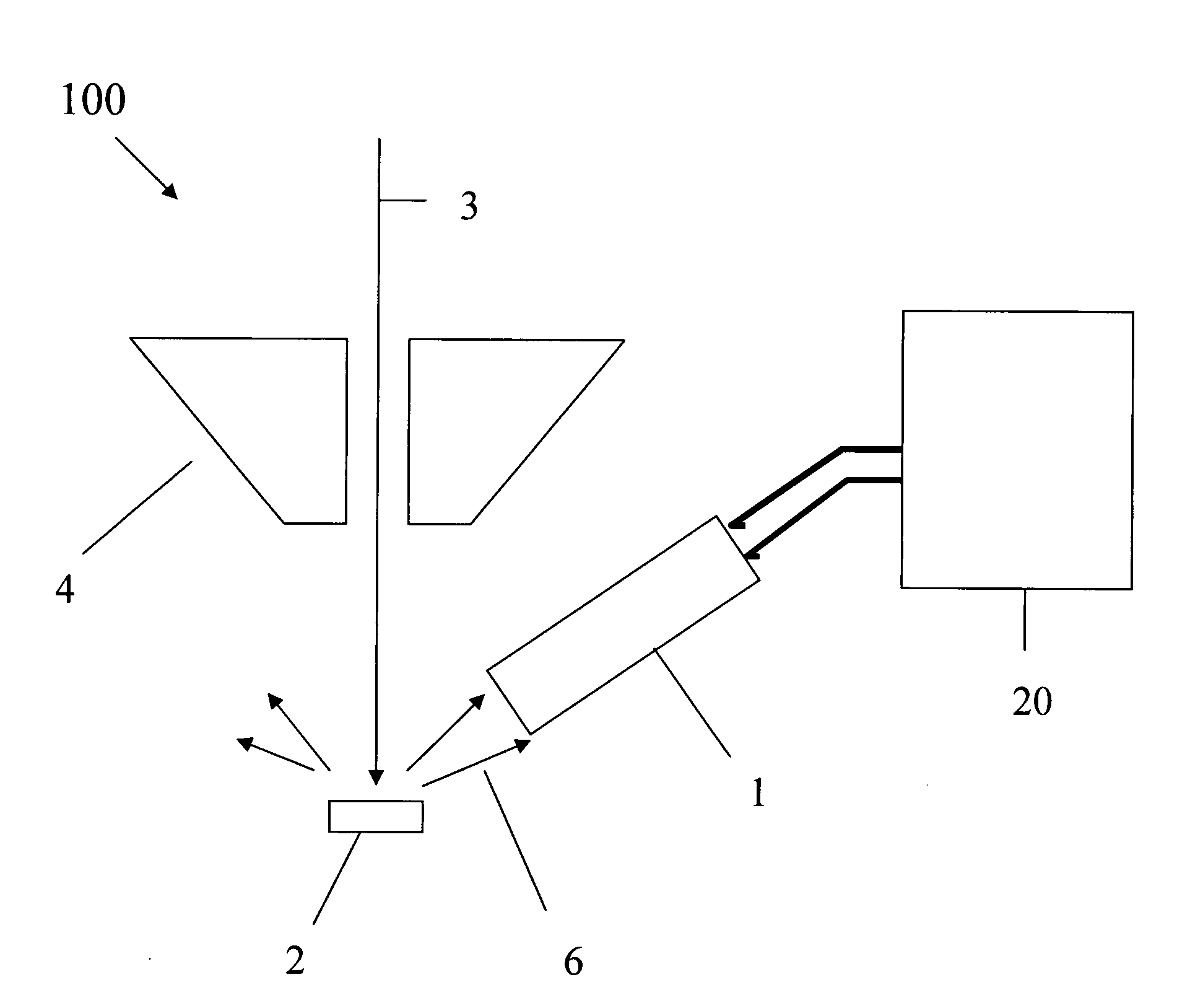
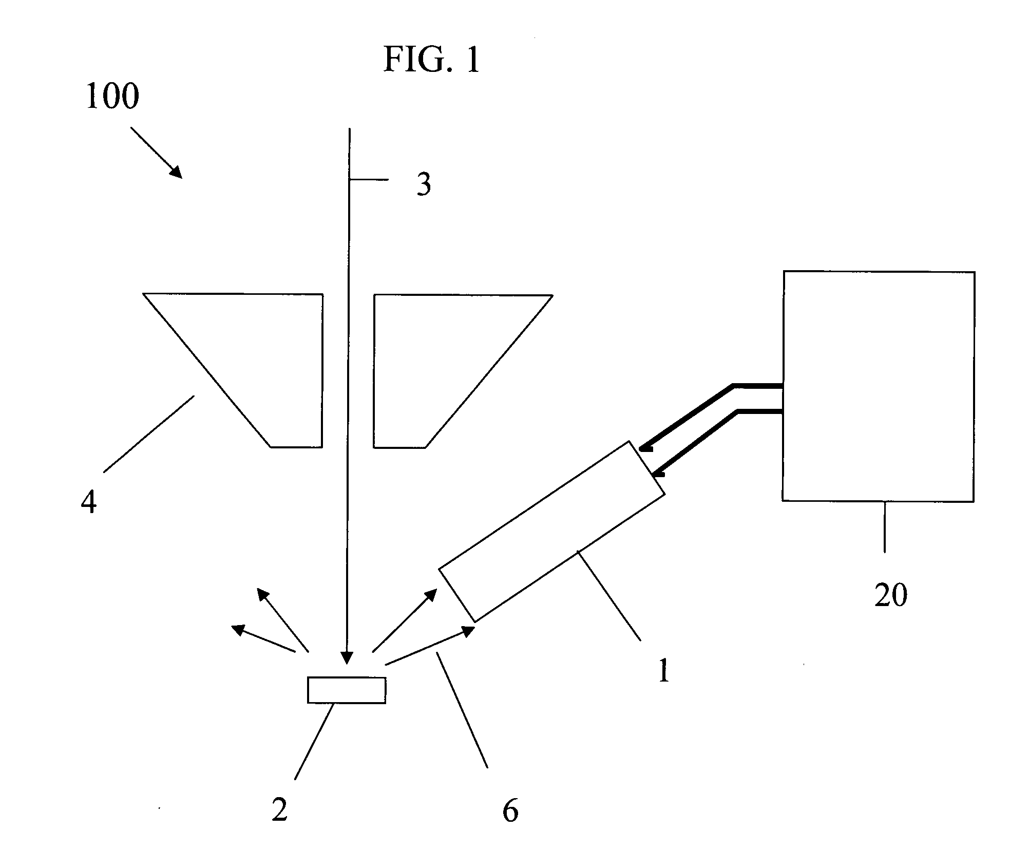
[0049]Referring to FIG. 1, the invention as embodied in this first example is a detection device (charged particle analyser) that has an entrance aperture that, when in use, is presented towards a sample 2 in a scanning electron microscope 100 from the same side as the incident electron beam 3. The incident beam consists of electrons that have been accelerated using a high voltage Vacc (typically 1 kV to 30 kV) and focused through a microscope lens 4. The electrons all strike the specimen with essentially the same energy. The specimen is typically earthed and incident electrons penetrate the sample 2 and are scattered.

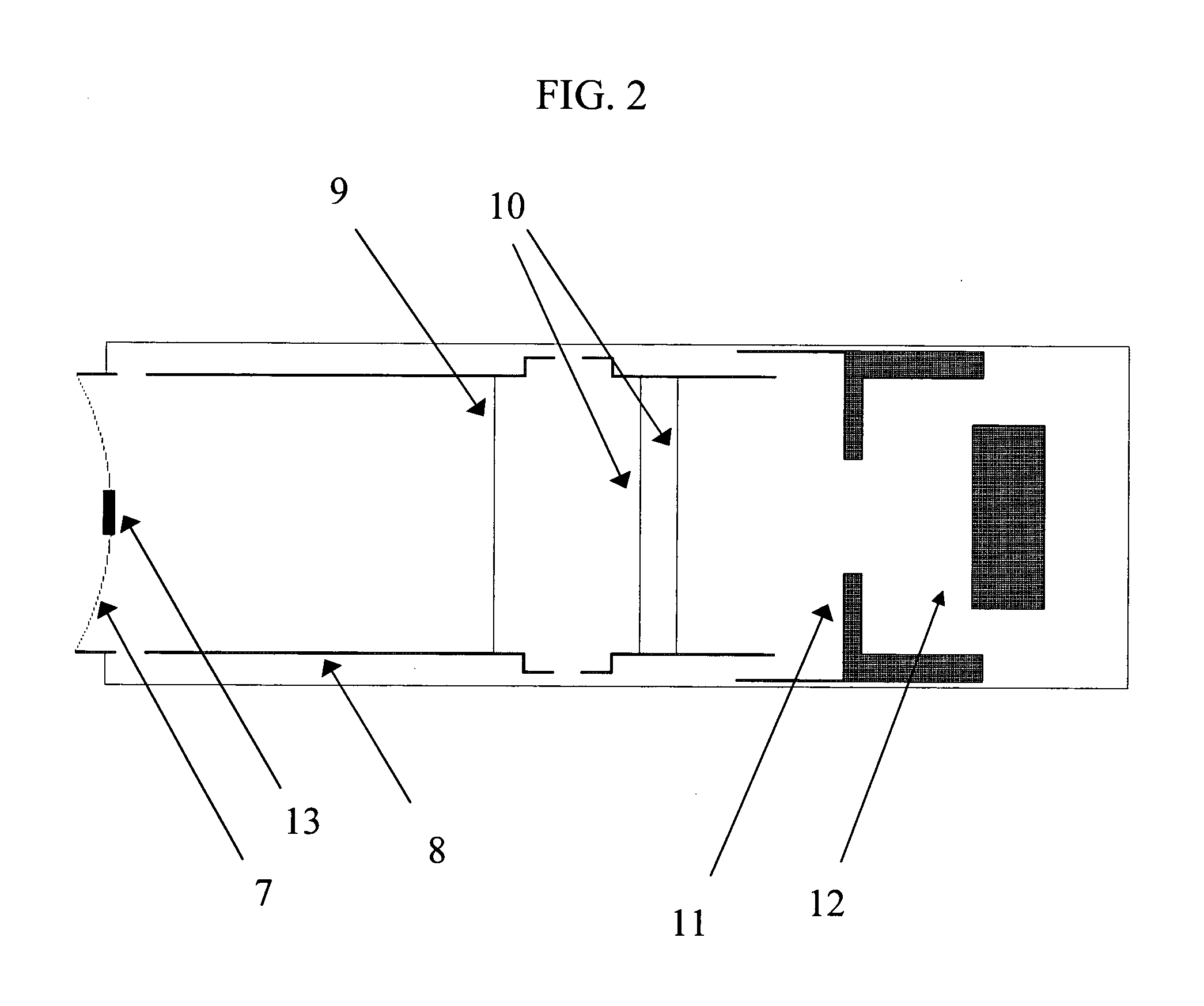
[0050]The detection device 1 uses a converging electrostatic lens to accept diverging electron trajectories 6 from a wide solid angle and redirect them down a tube towards a planar retarding grid such that they all strike the grid at approximately the same angle. With this arrangement the energy threshold at which electrons can get through the grid is similar for all t...


PUM


Abstract

A charged particle analyser (1) comprises a first non-imaging electrostatic lens (8, 9) for receiving charged particles having divergent, trajectories and for converting the said trajectories into substantially parallel trajectories. At least one planar filter (10) is provided for receiving the charged particles having the substantially parallel trajectories and for filtering the charged particles in accordance with their respective energies. A second non-imaging electrostatic lens (11) receives the energy filtered charged particles and selectively modifies their trajectories as a function of their energies. A charged particle detector (12) then receives the charged particles in accordance with their selectively modified trajectories.

Description

FIELD OF THE INVENTION[0001]The present invention relates to a charged particle analyser, a microscope including such an analyser and a method of using the analyser. The charged particle analyser finds use in many different analytical applications although in an electron analyser form it finds particular advantage when used with scanning electron microscopes (SEM). The analyser provides an improved signal detection and also high resolution image contrast based upon sampled composition. It also provides for new methods for material analysis based on the energy distribution of charged particles emitted from the specimen.BACKGROUND TO THE INVENTION[0002]A number of known analysers are now described, particularly in relation to the field of scanning electron microscopy.[0003]Scanning electron microscopes (SEMs) are common tools for the observation of small features. A finely focused electron beam (“probe”) with an energy typically between about 1 keV and 20 keV is scanned across the sur...

Claims


Application Information

Patent Timeline
IPC IPC(8): H01J37/28H01J37/12H01J47/00G01N23/22
CPCH01J37/05H01J37/256H01J37/28H01J49/488H01J2237/053H01J2237/24415H01J2237/2448H01J2237/24485H01J2237/2449H01J2237/24585H01J2237/2516
Inventor BARKSHIRE, IAN RICHARDSTATHAM, PETER JOHNJACKA, MARCUS
Owner OXFORD INSTR NANOTECH TOOLS
Why Eureka
Try Eureka