
Barrier layer for thin film battery

a barrier layer and thin film battery technology, applied in the direction of cell components, flat cell grouping, sustainable manufacturing/processing, etc., can solve the problems of detrimentally affecting the performance of thin film batteries, unsafe conditions, etc., to increase the achievable energy and power density, prolong the battery life, and enhance the efficiency of thin film battery packaging

Inactive Publication Date: 2010-07-29
CORNING INC
View PDF21 Cites 83 Cited by
  • Summary
  • Abstract
  • Description
  • Claims
  • Application Information

AI Technical Summary

Benefits of technology

[0001]The present invention relates generally to materials and processes for sealing thin film batteries, and specifically to a hermetic seal comprising a barrier layer formed from one or more of tin oxide, tin phosphate, tin fluorophosphate, chalcogenide glass, tellurite glass, and borate glass. The materials and processes described herein can be implemented to significantly enhance the efficiency of thin film battery packaging, which can extend battery lifetimes and increase achievable energies and power densities.
[0002]Thin film batteries function much in the same way as traditional batteries, but can have a total thickness less than 1 mm (e.g., 0.35 to 0.65 mm) and are suitable, for example, for low-voltage (1.5 to 3.0 V) applications where traditional button cell geometries may be inadequate. Because thin film batteries are rechargeable, their size need be no larger than required to satisfy the energy requirements for a single discharge, thus reducing weight and cost. Further, compared to traditional lithium-ion batteries, which comprise a liquid electrolyte core, thin film batteries have a solid state core that obviates concerns over electrolyte leakage and makes thin film batteries less vulnerable to overheating. Thin film batteries have a large range of operating temperatures that can extend, for example, from as low as −20° C. to as high as 130° C., and can be repeatedly charged and discharged with minimal detrimental effect. Based on these and other properties, thin film batteries have tremendous potential for applications in microelectronics and MEMS industries as active or stand-by power sources.
[0004]In semiconductor applications, thin film batteries can be deposited directly onto chips or chip packages in any desired shape or size. Power-paper batteries, for example, can be printed directly onto thin substrates such as paper, so they can be extremely flexible. Moreover, multiple thin film batteries can be fabricated into high density arrays of discrete units each having an areal footprint of, for example, about 0.25 to 1 mm2. Planar thin film batteries can be rolled or stacked into cylindrical or prismatic cell designs that can be packed together into modules. Such configurational flexibility allows multiple batteries to be connected in parallel or in series, depending on the application. By incorporating the barrier layer according to the invention, individually-packaged thin film batteries can be handled during and after device fabrication without adversely affecting failure rates.
[0005]Notwithstanding the foregoing, wide scale proliferation of thin film batteries depends on their meeting a number of additional challenges, including improved capacity, lower cycling losses, and increased lifetime. The lifetime of a thin film battery, for instance, can be affected by factors such as the thermal and electrochemical stability of the electrodes and the electrolyte, as well as the hermeticity of the battery package.
[0006]The desire for hermeticity is motivated primarily by the reactive nature of commonly-used alkali metal-based anodes, such as Li metal or Li6C and, in particular, the adverse reaction of these materials with air and water. Specifically, the reactions with air or water can create unsafe conditions and detrimentally compromise thin film battery performance. It is therefore desirable to minimize air or water exposure of the thin film battery layers and, in particular, the anode material both during and after fabrication.
[0009]These and other aspects and advantages of the invention can be achieved by a materials system and process for providing high performance encapsulation for thin film batteries. Such encapsulation can extend the lifetime of thin film batteries and particularly alkali metal-based thin film batteries by ensuring that the external environment is not the leading cause of failure. Specifically, high performance encapsulation layers according to the invention are incorporated into thin film batteries to hermetically seal the materials layers used to form the batteries and, specifically, alkali metal-based anode materials.

Problems solved by technology

Specifically, the reactions with air or water can create unsafe conditions and detrimentally compromise thin film battery performance.

Method used


Image

  • Barrier layer for thin film battery
  • Barrier layer for thin film battery
  • Barrier layer for thin film battery

Examples


examples

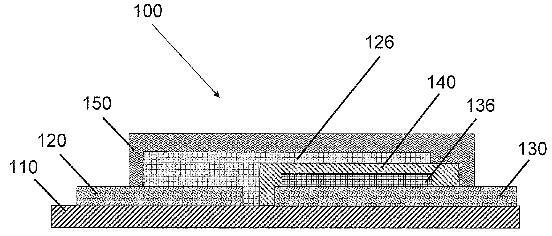
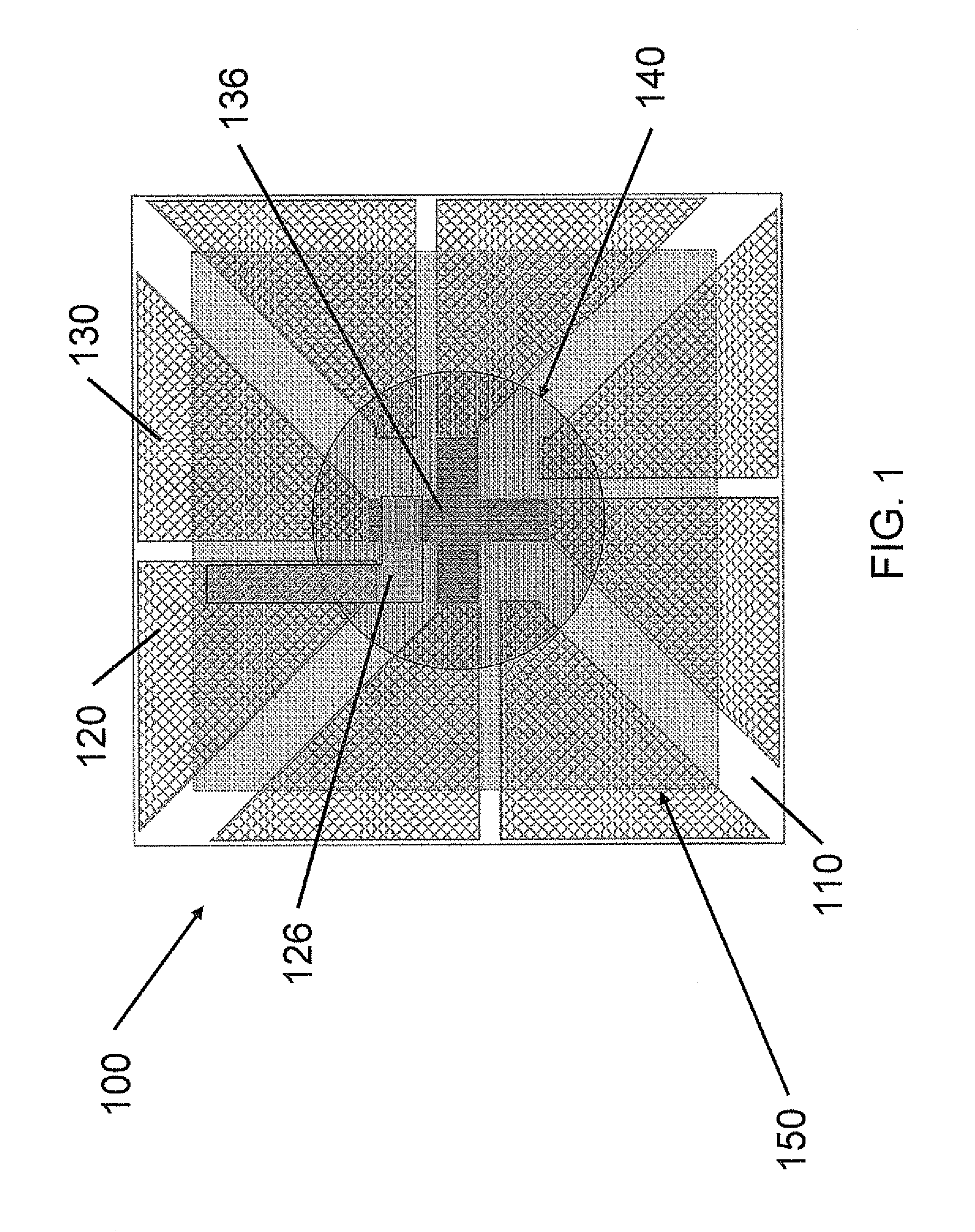
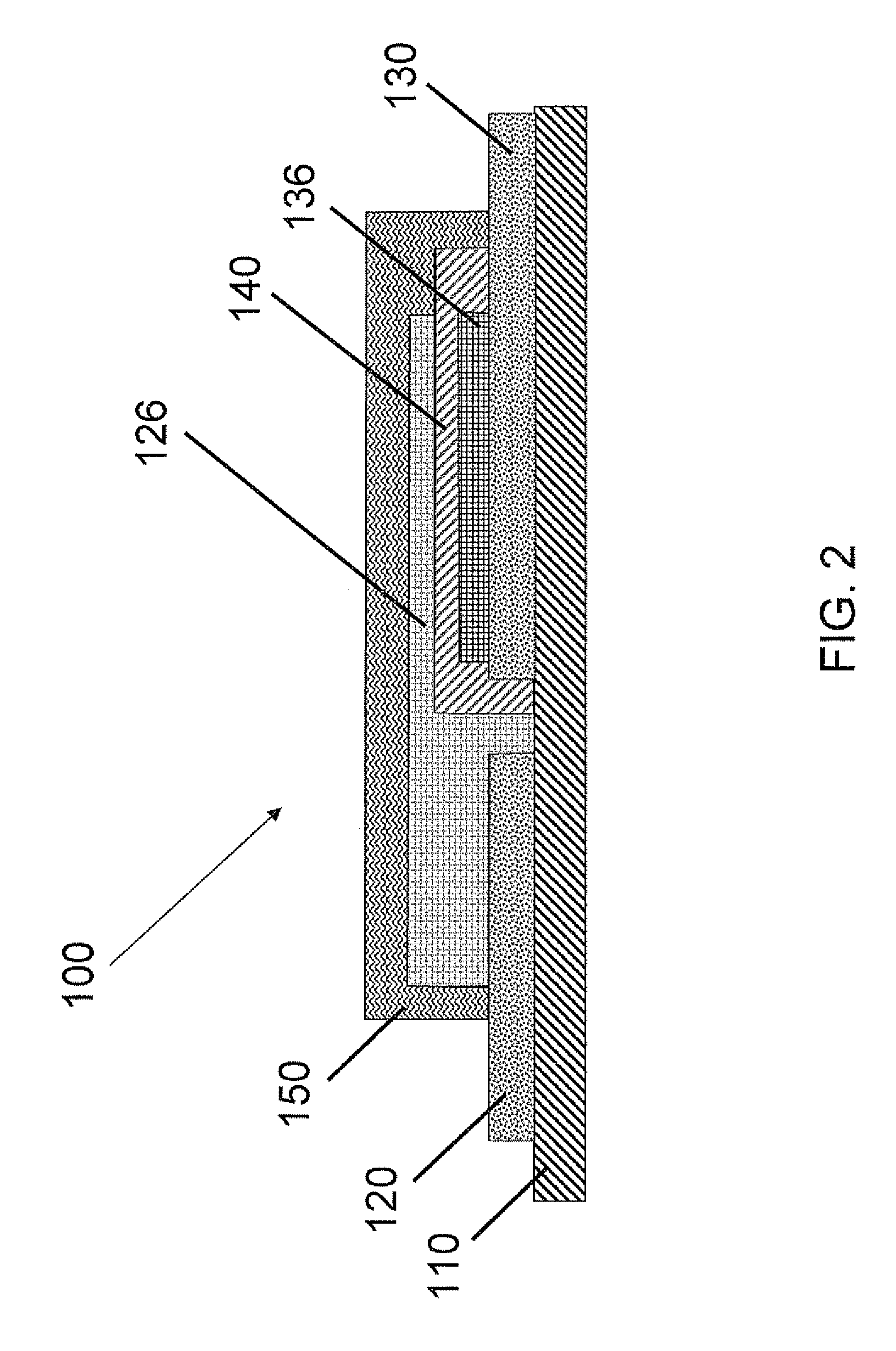
[0036]The invention will be further clarified by the following example. Again with reference to FIG. 2, a method of forming a thin film battery 100 comprising a barrier layer includes providing a substrate 110 having formed thereon separate patterned layers of indium tin oxide, which serve as both the anode and cathode current collectors 120, 130.

[0037]A cathode layer 136 is formed over the cathode current collector 130. The cathode layer 136, which may be formed by sputtering a pressed powder target of cathode material through a suitably patterned mask, may comprise LiCoO2 or, alternatively, LiMnO2, LiFeO2, LiNiO2 or V2O5, for example. In an RF magnetron sputter tool, exemplary sputtering conditions for forming a LiCoO2 cathode layer include a power of about 50 W, a chamber pressure of about 3 mTorr (e.g., 0.5 to 5 mTorr), and a sputter time of 1-3 hours in 100% pure argon. During sputtering of the target, the substrate can be maintained at a temperature of about −15-120° C. In ord...


PUM

PropertyMeasurementUnit
thicknessaaaaaaaaaa
thicknessaaaaaaaaaa
total thicknessaaaaaaaaaa

Abstract

A thin film battery comprises a substrate, anode and cathode current collector layers formed over the substrate, anode and cathode layers formed over and in electrical contact with respective ones of the current collector layers, and an electrolyte layer formed between the anode and cathode layers. The thin film battery further comprises a barrier layer formed from a material such as tin oxide, tin phosphate, tin fluorophosphate, chalcogenide glass, tellurite glass or borate glass. The barrier layer is configured to encapsulate the thin film battery layers and substantially inhibit or prevent exposure of the thin film battery layers to air or moisture.

Description

BACKGROUND AND SUMMARY[0001]The present invention relates generally to materials and processes for sealing thin film batteries, and specifically to a hermetic seal comprising a barrier layer formed from one or more of tin oxide, tin phosphate, tin fluorophosphate, chalcogenide glass, tellurite glass, and borate glass. The materials and processes described herein can be implemented to significantly enhance the efficiency of thin film battery packaging, which can extend battery lifetimes and increase achievable energies and power densities.[0002]Thin film batteries function much in the same way as traditional batteries, but can have a total thickness less than 1 mm (e.g., 0.35 to 0.65 mm) and are suitable, for example, for low-voltage (1.5 to 3.0 V) applications where traditional button cell geometries may be inadequate. Because thin film batteries are rechargeable, their size need be no larger than required to satisfy the energy requirements for a single discharge, thus reducing weig...

Claims


Application Information

Patent Timeline
Patent Type & Authority Applications(United States)
IPC IPC(8): H01M6/12H01M6/02C23C14/34H01M50/209
CPCH01M2/1061H01M6/40H01M10/0436H01M10/052Y10T29/49108H01M10/0565H01M10/0585Y02E60/122H01M10/0525Y02E60/10H01M50/209Y02P70/50
Inventor AITKEN, BRUCE GARDINERST. CLAIR, TODD PARRISHLIM, JAMES R.MAZUMDER, PRANTIKQUESADA, MARK ALEJANDRO
Owner CORNING INC
Learn More