Extreme ultraviolet light source apparatus and cleaning method

a light source and ultraviolet light technology, applied in the direction of condensers, process and machine control, instruments, etc., can solve the problems of reducing the sensitivity of the optical sensor, the reflection or transmittance of the optical element is reduced, and the output of euv light is reduced, so as to prolong the life of the optical element, the effect of easy and efficient removal

Inactive Publication Date: 2010-08-05
GIGAPHOTON
View PDF11 Cites 67 Cited by
  • Summary
  • Abstract
  • Description
  • Claims
  • Application Information

AI Technical Summary

Benefits of technology

[0016]The present invention has been achieved in view of the above-mentioned problems. A purpose of the present invention is to provide an extreme ultraviolet light source apparatus that can eliminate debris adhering to a component such as optical elements provided within a chamber, especially, to a reflection surface of an EUV collector mirror. Another purpose of the present invention is to provide a cleaning method to be used in the extreme ultraviolet light source apparatus.
[0019]Here, the cleaning pulse laser beam may be a pulse laser beam having a wavelength within a range from a vacuum ultraviolet range to an infrared range. Especially, it is preferable that the cleaning pulse laser beam is a pulse laser beam having a wavelength in an ultraviolet range in that the pulse laser beam causes little damage on the multilayer coating of the EUV collector mirror and debris can be efficiently removed.
[0020]When the reflection surface of the EUV collector mirror to which debris adheres is irradiated with the pulse laser beam, the debris adhering to the reflection surface can be efficiently removed without causing damage on the multilayer coating of the reflection surface. The reason for that is as follows. The adherent particles (debris) rapidly thermally expand by the energy of the pulse laser beam. Accordingly, acceleration of the adherent particles is generated relative to a material to which the particles adhere. It is considered that the acceleration eliminates the intermolecular force between the adherent particles and the material to which the particles adhere, and thereby, liberate and remove the adhering particles.
[0021]According to the present invention, debris can be easily and efficiently removed even at a room temperature and under the condition of vacuum or low vacuum without the need of various incidental technologies such as measures to deal with etchant gas, an etching stimulation plasma unit, an ion acceleration unit, higher temperature of the EUV collector mirror, and so on. Further, by optimizing the irradiation intensity of the pulse laser beam, only the adhering debris can be removed without causing damage on the EUV collector mirror. In this manner, the debris adhering to the surface of the optical element such as the EUV collector mirror is removed, and thereby, the lifetime of the optical element can be extended and the cost of the apparatus can be reduced.

Problems solved by technology

Accordingly, the reflectivity or transmittance of the optical elements becomes lower, and a problem that the output of EUV light becomes lower and a problem that the sensitivity of the optical sensor becomes lower occur.
Especially, since the EUV collector mirror is provided to surround the plasma near thereto, neutral particles emitted from the plasma or the target adhere to the reflection surface of the EUV collector mirror, which reduces the reflectivity of the EUV collector mirror, while ions emitted from the plasma scrape off the multilayer coating formed on the reflection surface of the EUV collector mirror by the sputtering action, which reduces the selectivity of the EUV light.
The EUV collector mirror is very expensive because it is necessary to perform special surface treatment on the reflection surface and high optical accuracy such as high flatness of about 0.2 nm (rms) is required, for example.
Accordingly, it is difficult to maintain focusing ability of the EUV light and the driver pulse laser beam.
However, the ultraviolet light does not photochemically react with a metal such as tin, and has no effect on the metal coating adhering to the EUV collector mirror.

Method used


Image

  • Extreme ultraviolet light source apparatus and cleaning method
  • Extreme ultraviolet light source apparatus and cleaning method
  • Extreme ultraviolet light source apparatus and cleaning method

Examples


embodiment 1

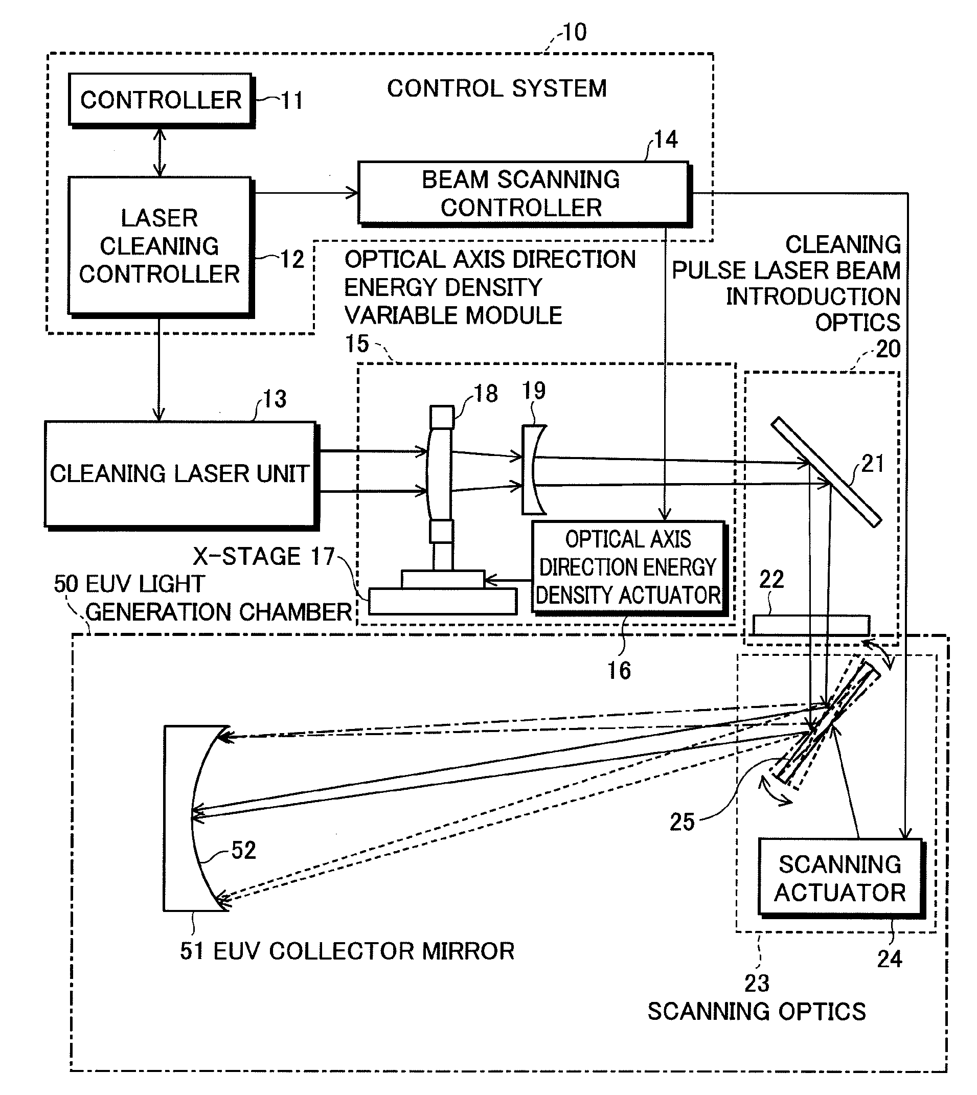
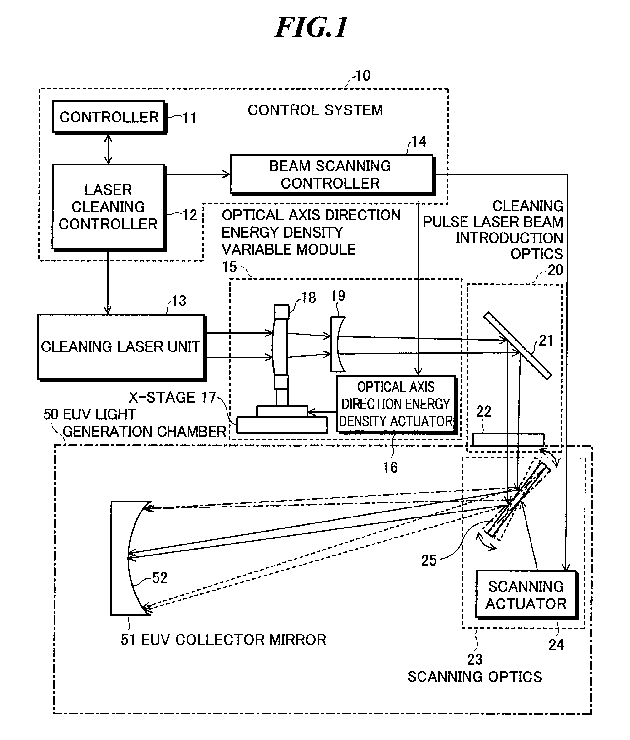
[0045]FIG. 1 shows a configuration of a laser cleaning apparatus in an LPP type EUV light source apparatus according to the first embodiment of the present invention. The configuration other than the laser cleaning apparatus is the same as that of an LPP type EUV light source apparatus according to the second embodiment as shown in FIG. 5, for example.

[0046]The LPP type EUV light source apparatus according to the first embodiment removes debris by scanning a reflection surface 52 of an EUV collector mirror 51 having a spheroidal shape at predetermined energy density by using the laser cleaning apparatus. For the purpose, the laser cleaning apparatus includes a cleaning laser unit 13 for emitting a cleaning pulse laser beam, an optical axis direction energy density variable module 15 for controlling the convergence state of the cleaning pulse laser beam such that energy density in the optical axis direction of the cleaning pulse laser beam falls within a predetermined range, a cleani...

embodiment 2

[0067]FIG. 5 shows a configuration of an LPP type EUV light source apparatus according to the second embodiment of the present invention. The LPP type EUV light source apparatus as shown in FIG. 5 includes a control system 10, a laser cleaning apparatus similar to that in the first embodiment as shown in FIG. 1, an EUV light generation chamber 50, an EUV collector mirror 51, a target supply unit 53, a target collecting unit 54, a driver laser unit 57, a focusing optics 58 for a driver pulse laser beam, a laser dumper 60 for the driver pulse laser beam, a spectrum purity filter (SPF) 61, a pinhole plate 63, a gate valve 64, and two electromagnets 75.

[0068]The laser cleaning apparatus includes a cleaning laser unit 13, an optical axis direction energy density variable module 15, and a scanning optics having an HR mirror 21 and a scanning mirror (rotating mirror) 25. The pulse laser beam emitted from the cleaning laser unit 13 is introduced into the EUV light generation chamber 50 via ...

embodiment 3

[0093]FIG. 12 shows a configuration of an LPP type EUV light source apparatus according to the third embodiment of the present invention. The EUV light source apparatus according to the third embodiment includes a far-field detector 26 for detecting a far-field pattern of the EUV light in order to observe a debris adhering region (condition) on the reflection surface 52 of the EUV collector mirror 51. The rest of the configuration is the same as that of the second embodiment as shown in FIG. 5. Generally, the far-field pattern is defined as an irradiation distribution pattern (beam pattern) of the EUV light that spreads in a farther position from the first focal position 56 than the second focal position (IF) 62 to which an image of the EUV light in the first focal position 56 of the EUV collector mirror 51 is transferred.

[0094]In the embodiment, a spectrum purity filter (SPF) 66 is provided between the EUV collector mirror 51 and the IF 62, and a beam pattern in the farther positio...


PUM

PropertyMeasurementUnit
wavelengthaaaaaaaaaa

Abstract

An extreme ultraviolet light source apparatus that can eliminate debris adhering to a component such as optical elements provided within a chamber. The extreme ultraviolet light source apparatus includes: a chamber in which extreme ultraviolet light is generated; a target material supply unit for supplying a target material into the chamber; a driver laser unit for irradiating the target material with a driver pulse laser beam to generate plasma; a cleaning laser unit for emitting a cleaning pulse laser beam; and a control unit for controlling an irradiation position of the cleaning pulse laser beam emitted from the cleaning laser unit so as to irradiate a component provided within the chamber with the cleaning pulse laser beam to remove debris adhering to a surface of the component.

Description

CROSS-REFERENCE TO RELATED APPLICATION[0001]The present application claims priority from Japanese Patent Application No. 2009-008356 filed on Jan. 19, 2009, the contents of which are incorporated herein by reference in their entirety.BACKGROUND OF THE INVENTION[0002]1. Field of the Invention[0003]The present invention relates to an extreme ultraviolet (EUV) light source apparatus to be used as a light source of exposure equipment, and a method of cleaning a component provided within a chamber, in which EUV light is generated, in the EUV light source apparatus.[0004]2. Description of a Related Art[0005]In recent years, as semiconductor processes become finer, photolithography has been making rapid progress toward finer fabrication. In the next generation, microfabrication at 60 nm to 45 nm, further, microfabrication at 32 nm and beyond will be required. Accordingly, in order to fulfill the requirement for microfabrication at 32 nm and beyond, for example, exposure equipment is expect...

Claims


Application Information

Patent Timeline
Patent Type & Authority Applications(United States)
IPC IPC(8): B08B7/00H05H1/00B05D3/06
CPCB08B7/0042G02B19/0028G02B27/0006G02B27/0955G02B27/20G03F7/70033G03F7/70525G03F7/7085G03F7/70916G03F7/70925G03F7/70941H05G2/003H05G2/008G02B19/0095G02B19/0052G02B26/101
Inventor UENO, YOSHIFUMIWAKABAYASHI, OSAMU
Owner GIGAPHOTON
Why Eureka
Try Eureka