
Heat Pipe with Nanostructured Wick

a nano-structured, heat pipe technology, applied in indirect heat exchangers, semiconductor/solid-state device details, lighting and heating apparatus, etc., can solve the problems of increasing fluid flow, significantly reducing the thermal resistance of the nano-bristle structure, etc., to achieve no operating cost, high efficiency, and more efficient

Inactive Publication Date: 2010-08-12
ILLUMINEX CORP
View PDF14 Cites 92 Cited by
  • Summary
  • Abstract
  • Description
  • Claims
  • Application Information

AI Technical Summary

Benefits of technology

[0008]The significant advantage possessed by the nanowire device is that the boiling surface area available in the nanowire array can be well in excess of 1000 cm2 per square centimeter of the surface area of the heat pipe surface that it occupies. This is to be compared with boiling surface areas of only a few cm2 per cm2 in grooved heat pipes and a few tens of cm2 in sintered metal powder devices. This enhancement to the surface area can potentially result in a several fold improvement in heat flux transport enabling devices that can remove up to several hundred W / cm2.
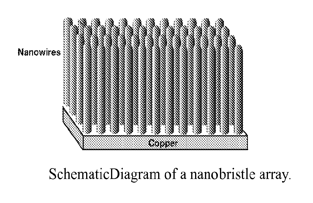
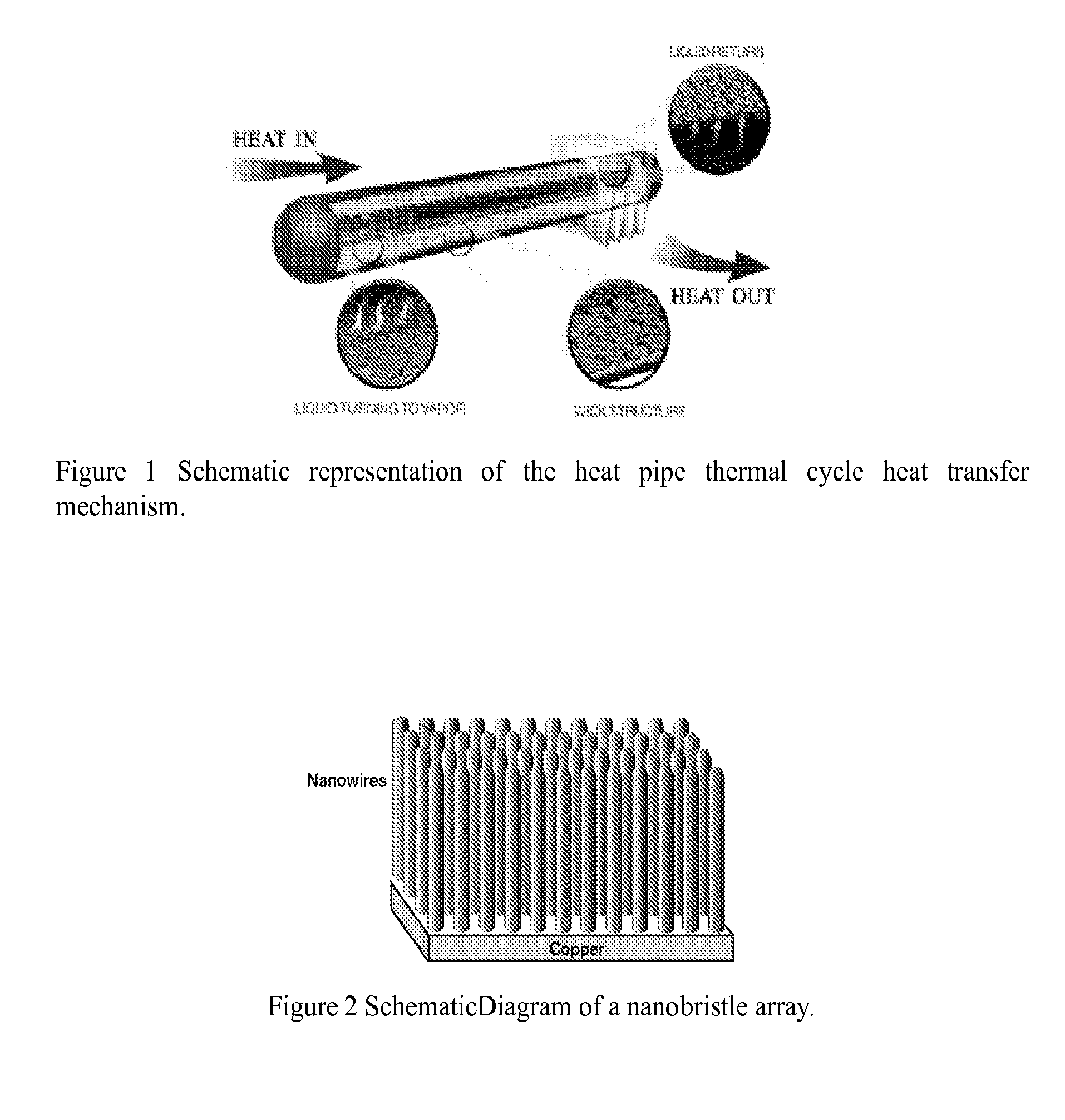
[0009]Nanobristle arrays (shown schematically in FIG. 2) have significant attributes that make them advantageous as the wick material in heat pipes. The tight packing of the bristles in the array provides a high capillary pressure to promote fluid flow through the wick while the aligned array configuration of the bristles provides a clear path for vapor to escape. Thus the nanobristle architecture can significantly decrease the thermal resistance and increase the fluid flow compared to currently used sintered powder copper, screen, or axially grooved wicks. These two attributes of the nanobristle array improves the heat flux capacity of heat pipe devices to greater than 300 W / cm2. Heat fluxes of approximately 25 W / cm2 to 125 W / cm2 with a thermal resistance less than 0.06° C.-cm2 / W , have been observed.
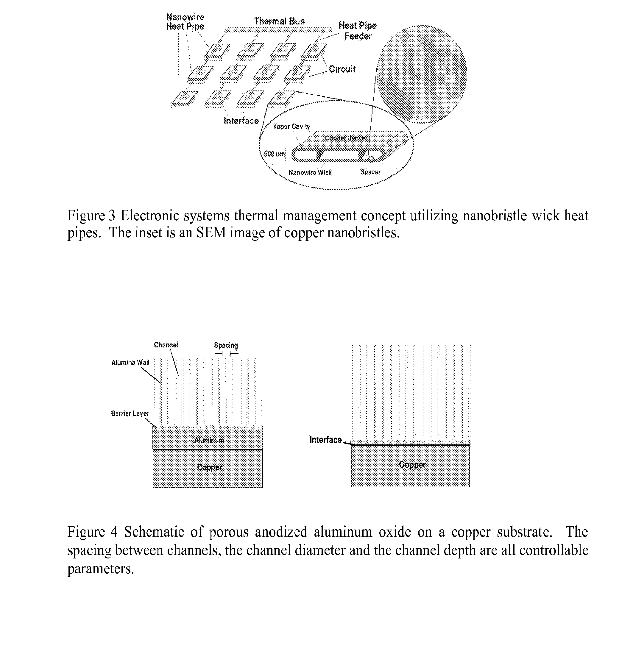
[0010]The nanobristle array wick allows the height, or profile, of the entire heat pipe to be reduced to less than 1 mm (0.040″) and can be used where conventional heat pipe devices and cooling technologies are inadequate. This is critical for portable electronic devices that utilize ever increasingly powerful (heat generating) processors in smaller and smaller packages. FIG. 3 schematically shows a thermal bus architecture utilizing nanobristle heat pipe technology as the key link between the high power circuits and the external thermal bus.
[0011]The current heat pipe technology typically limits the wicking structure to a minimum thickness of 1 mm to provide adequate cooling. Thus, the heat pipe has to be greater than about 2 mm thick, plus packaging, plus evaporation space. Typically, 5 mm in width is a minimum dimension. To get any smaller, the wicking structure has to be smaller. The current invention can be used to create wicking structures that are only about 50-100 microns (10× improvement) in bristle wick length, thus making it possible for a 300 micron width copper layer sufficient to enclose the heat pipe volume while still providing the same heat transport capacity. The invention permits a heat pipe with a 900 micron cross section or less. This reduces weight and size for the same amount of heat transfer efficiency. In addition to improvements in weight and size, the nano-structured wicking material exhibits improved capillary action and lower thermal resistance. The bristle structures are arrayed. The bristles have a uniform size and spacing that can be controlled to optimize the capillary action and thermal resistance for a particular application. A 35% to 50% reduction in thermal resistance than sintered copper powder wicks can be achieved by means of the use of nanostructured wicking materials. Sintered copper powder is the industry preference and currently exhibits the lowest thermal resistance of all currently commercially distributed heat pipe wick structures.
[0012]Other key features of the nanowire array heat pipe are that it can be built with an extremely thin profile and that the nanowire wick will enable operation at any orientation. Devices less than 1 mm thick can be built that can be directly incorporated into high power component packages. This design flexibility can enable the top of the heat pipe to be specifically designed to incorporate a coupling structure so that the device can be efficiently mated to a thermal (heat pipe) bus as well as the device to be cooled.PRIOR ART

Problems solved by technology

Thus the nanobristle architecture can significantly decrease the thermal resistance and increase the fluid flow compared to currently used sintered powder copper, screen, or axially grooved wicks.

Method used


Image

  • Heat Pipe with Nanostructured Wick
  • Heat Pipe with Nanostructured Wick
  • Heat Pipe with Nanostructured Wick

Examples


case # 1

Case #1: if C=20 nm, D=10 nm, L=1 μm, BSR=125.6

Case #2: If C=250 nm, D=200 nm, L=100 μm, BSR=1962.5

case # 3

Case #3: If C=100 nm, D=60 nm, L=200 μm, BSR=3600

[0059]In this case, BSR is calculated based on only the outer cylindrical area of the nanowires.

For case #2, on a 1 cm piece of material, the nanowire tips occupy about 0.50 cm2, justifying their exclusion from the calculation.

[0060]By lengthening the nanowires and placing them on narrower spacing one can get the BSR up to approximately 3,600, that is, Case #3. Typical sintered metal powder wicks exhibit a BSR of about 35. The wicking material disclosed in U.S. Pat. No. 4,015,659 discloses a material with a BSR estimated to be approximately 5 to approximately 50, depending on a range of whisker length of 100 microns to 1 millimeter. Practitioners of ordinary skill will recognize that if the length of the nanowire is too long relative to its diameter, then it is more likely to crack or otherwise fail. In the preferred embodiment, the aspect ratio of the nanowires should be less than approximately 2500 to 1. The aspect ratio is defined ...


PUM

PropertyMeasurementUnit
Temperatureaaaaaaaaaa
Lengthaaaaaaaaaa
Lengthaaaaaaaaaa

Abstract

A heat pipe with a nanostructured wick is disclosed, with the method of forming the nanostructured wick on a metal substrate. The wicking material is a pattern of metallic nanostructures in the form of bristles or nanowires attached to a substrate, where the bristles are substantially freestanding.

Description

[0001]This application claims priority to U.S. Pat. App. No. 66 / 778,873, filed on Mar. 3, 2006, which is hereby incorporated herein by reference for all that it teaches and to U.S. Pat. App. No. 60 / 888,391, filed on Feb. 6, 2007, which is hereby incorporated herein by reference for all that it teaches.[0002]This invention was supported in part by U.S. Government contract number Phase I SBIR Navy Contract N65540-03-0055 and NSF Phase 165618840 and portions of this invention may be subject to a paid-up license to the U.S. Government.BACKGROUND AND SUMMARY OF THE INVENTION[0003]Heat pipes are the method of choice for electronic systems thermal management because of the performance advantages they have over conventional aluminum extrusion heat sinks and other solid state cooling technologies. A heat pipe cooler uses the high efficiency evaporation and condensation cycles of a working fluid to transfer heat as shown in FIG. 1. Compared to other cooling techniques, such as forced single a...

Claims


Application Information

Patent Timeline
IPC IPC(8): F28D15/04B21D53/02
CPCB82Y30/00C25D7/00C25D11/02F28D15/046Y10T29/49353H01L23/427H01L2924/0002F28F13/185H01L2924/00
Inventor HABIB, YOUSSEF M.RICKARD, LYMAN H.JOHN, BRYAN G.STEINBECK, JOHN W.
Owner ILLUMINEX CORP
Learn More