Resonant sensors and methods of use thereof for the determination of analytes

a technology of resonance sensors and analytes, which is applied in the direction of resonant frequency, vibration measurement in solids, instruments, etc., can solve the problems of inability to make analyte determinations, inability to use the base non-piezoelectric layer, and inability to sensitive techniques

Inactive Publication Date: 2010-08-19
LEVERSENSE
View PDF88 Cites 25 Cited by
  • Summary
  • Abstract
  • Description
  • Claims
  • Application Information

AI Technical Summary

Benefits of technology

[0012]In accordance with one aspect of the present invention, there is provided a resonant sensor for determining the presence, amount or binding kinetics of an analyte in a test medium. The sensor is operable under the influence of an activating force field and comprises an active, deformable planar member that serves as a sensing element, having a resonant mode for analyte determination and one or more axis of symmetry. The sensor also compris

Problems solved by technology

Although widely used, these techniques are not very sensitive and require extensive sample preparation, especially with complex or unpurified biological samples.
Moreover, most biosensing platforms now in commercial use are not capable of making analyte determinations by measuring changes in mass on a sensor surface.
Deformation occurs primarily along the planar dimensions of the PZT layer, because of geometrical and associated constraints, causing the base non-piezoelectric layer to flex.
Thus, QCM analysis is of limited value when the analyte is present at low concentration together with a high level of contaminants.
Consequently, the stiffness of the “finger” and base will be identical so that resonant frequency modes, observed by changes in the “finger” impedance will be highly complicated and minimally useable.
Although the piezoelectric cantilever sensors of the prior art are satisfactory in many respects, the excess length resulting from the overlap between the piezoelectric layer and non-piezoelectric layer adds parasitic geometry to the s

Method used


Image

  • Resonant sensors and methods of use thereof for the determination of analytes
  • Resonant sensors and methods of use thereof for the determination of analytes
  • Resonant sensors and methods of use thereof for the determination of analytes

Examples


example 1

[0066]Sensors were fabricated using 125 um PZT and 125 alumina. The materials were wafer bonded using epoxy or solder and subsequently diced to singulate individual sensor assemblies creating sensors with coextensive symmetry and asymmetry. The dimensions evaluated ranged from 0.75 to 1.25 mm wide and up to 6 mm long. Electrode wires were soldered and fixed with conductive epoxy. Sensors were fabricated “floating” and anchored in epoxy. The resonant frequency, associated spectrum and signal quality (Q) were examined using an impedance analyzer. The sensor variations built verified behavior expected from finite element modeling.

example 2

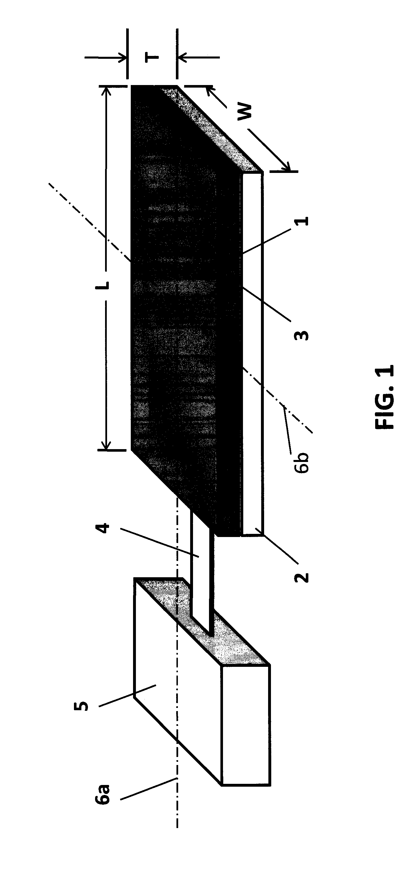
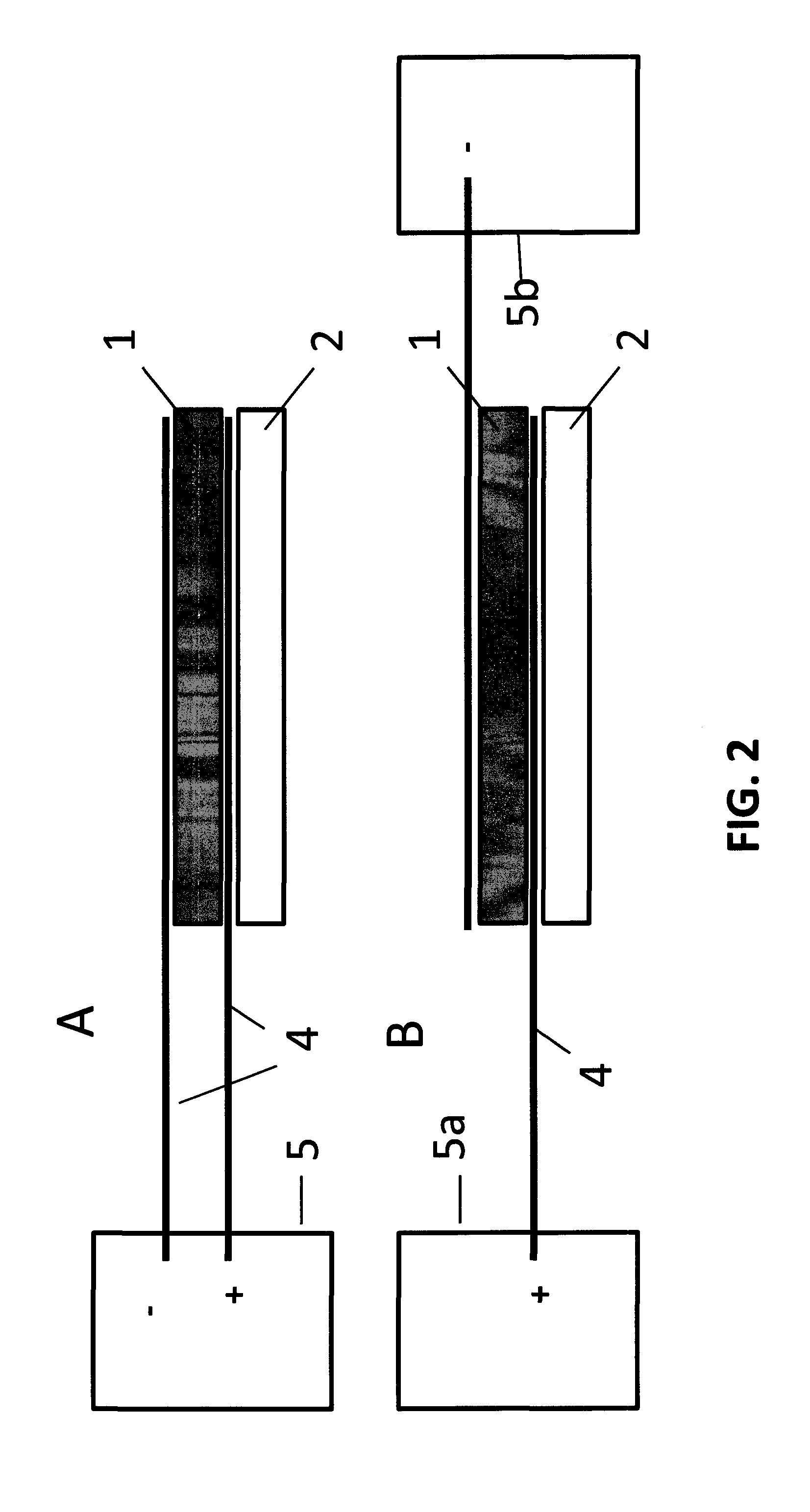
[0067]Devices were fabricated ranging from 1.5×1 mm to 2.0×1 mm in which the active and passive planar members were coextensive, having equal length and width. Two different methods were successfully used to fabricate these devices. In one method, a 1.5×1 mm PZT layer having a thickness of 125 μm, which served as the active member, was joined to a passive, alumina layer having the same dimensions. The alumina layer was metalized and soldered to the PZT layer. The alumina layer had a solder filled via which allowed for electrodes to be attached to either side of the assembly. The electrodes were metal strips and were attached with conductive epoxy. The structure of the resulting device corresponds generally to that illustrated in FIG. 1. This device produced the spectrum shown in FIG. 9. An alternate assembly method was also successfully used, substituting glass for alumina as the passive member, which was attached to the PZT layer by means of epoxy. A metal strip electrode was attac...


PUM


Abstract

Resonant sensors, preferably having floating bilayer symmetry, and their methods of use is determining the presence, amount or binding kinetics of an analyte of interest in a test sample are disclosed. The test sample may be a liquid or gas.

Description

CROSS-REFERENCE TO RELATED APPLICATIONS[0001]The present application claims the benefit of U.S. Provisional Patent Application No. 61 / 153,119, filed Feb. 17, 2009, the entire disclosure of which is incorporated by reference herein.BACKGROUND OF THE INVENTION[0002]The present invention relates to resonant sensors and in particular to biosensors useful for the qualitative and quantitative determination of one or more analytes, e.g., a specific protein, carbohydrate, glycoprotein, protein complex, nucleic acid molecules, (DNA and RNA) mycoplasma, virus, bacterium, yeast, mammalian cell, parasites, cysts, prions, or phospholipid, in a test sample suspected of containing such analyte(s).[0003]A host of analytical techniques have been developed for the detection of biomolecules, pathogens and the like. Such techniques include surface plasmon resonance (SPR), polymerase chain reaction (PCR), enzyme-linked immunoassay (ELISA), and immuno-magnetic beads, to name a few. Although widely used, ...

Claims


Application Information

Patent Timeline
IPC IPC(8): G01R23/00
CPCG01N29/022G01N29/036G01N29/2437G01N2291/012Y10T436/143333G01N2291/0256G01N2291/0427Y10T436/255G01N2291/0255
Inventor LOVERICH, JACOB J.FRANK, JEREMY E.NAGY, PETER A.
Owner LEVERSENSE
Why Eureka
Try Eureka