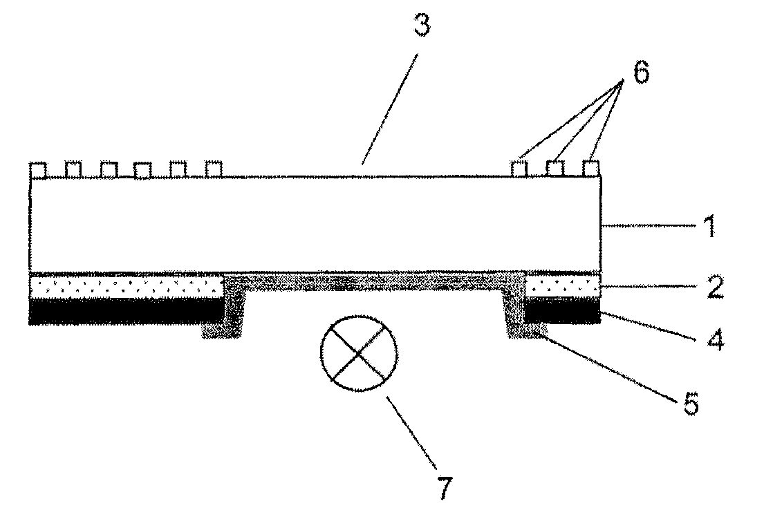
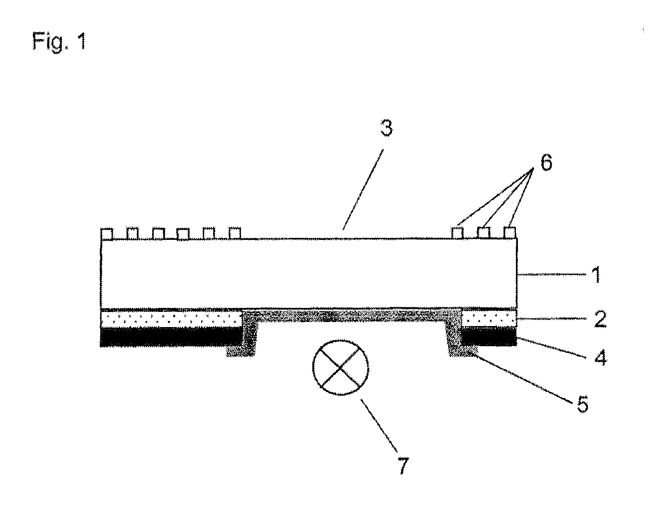
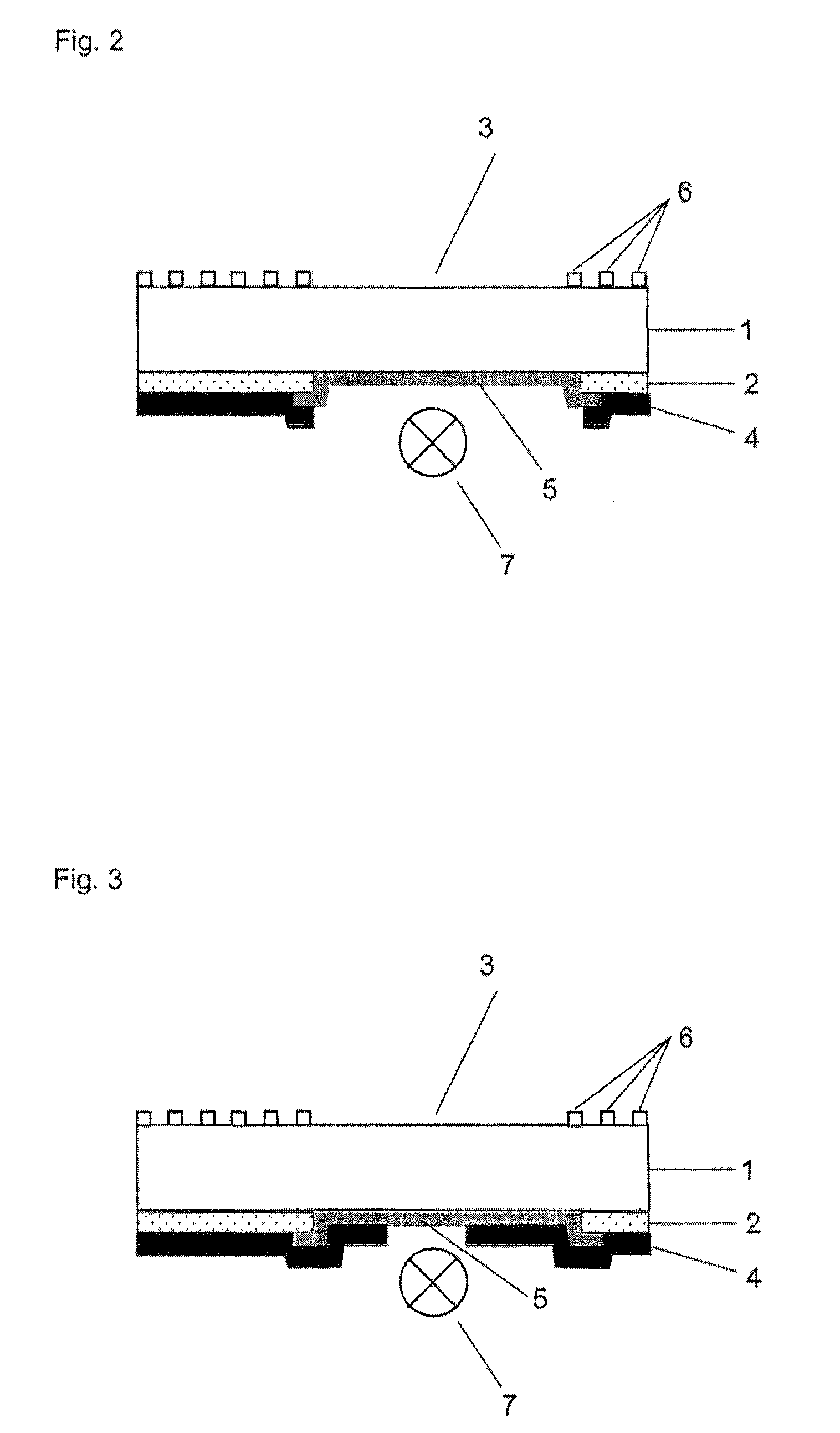
[0025]The overlapping printing of the display layer on the coating of the surrounding region is advantageous since, owing to manufacturing tolerances, the accuracy with which the template for printing of the display layer can be aligned relative to all other previously printed
layers (including upper side decor) is usually 0.3-1.0 mm. Without overlap with the surrounding underside coating, regions of the display window could remain uncoated due to offsetting of the template because of the manufacturing tolerances. However, if a sufficiently large overlap of the display layer with the surrounding coating is provided, it can be ensured that the entire display region is always completely filled by the display layer.
[0027]On the other hand, adhesion problems occur when the surrounding layer contains predominantly (more than 50% by weight based on the dry layer) of silicones (polysiloxanes) as binding agents. In this case, the interlaminar adhesion can be improved when from 0.5 to 10% by weight, in particular cases up to 30% by weight, of
silicone are added to the display layer. At
silicone contents higher than 30% by weight, the scratch resistance drops to below 100 g. The added
silicone also increases the impermeability of the display layer towards water, oil and other liquids, as a result of which the tendency of the display layer to form spots on contact with liquids is decreased. The
adhesive strength can be tested by means of the “TESA test” in which a strip of
transparent adhesive tape is rubbed onto the coating and then pulled off with a jerk (Tesafilm type 104, Beiersdorf AG). If the coating cannot be detached from the glass-ceramic by means of the
adhesive tape, so that no damage is visible to the user, then the underside coating adheres sufficiently strongly.
[0031]Such a sol is virtually colorless after
drying or baking. In order to reduce the light
transmittance of the coating, the addition of pigments is therefore necessary. Pigments which are thermally stable up to 200° C. at least briefly (1-10 minutes) are suitable. The display coating normally does not have to withstand higher temperatures, firstly because the 7-segment display devices or LCD visual display units located underneath do not permit higher temperatures and such display areas are therefore provided in the cold region of the cooking surface and secondly because touch sensors are usually arranged in the vicinity of the display regions and the cooking surface has to be colder than 60° C. in the region of the switches so that the user's fingers are not burnt when operating the cooking surface.
[0046]The scratch resistance of the coating is highest when very complete crosslinking between the reactive groups, in particular the alkoxysilane groups and the hydroxy groups, takes place during baking without the organic groups bound directly to
silicon (e.g.
aryl or
alkyl groups) being thermally eliminated. The
elimination of these organic groups which modify the
silicon oxide framework and are not intended for a
condensation reaction usually takes place only at above 200° C. (more often above 250° C.). A temperature of 200° C. should therefore not be exceeded during baking so that the scratch resistance of the display layer is maximized. The scratch resistance of the display
layers obtained by the process described above is at least 100 g, in particular cases even 200 g.
[0048]When the cooking surface, coated on the underside should be suitable for capacitively operating touch sensors (e.g. touch control units), it is necessary for the alkyl
silicate coating in the display region to be electrically nonconductive, i.e. the electrical surface resistance of the display coatings should be in the megaohm, better in the gigaohm, range (at above 109 Ω / square). This property is achieved by avoiding
electrically conductive pigments (e.g.
metal powders,
aluminium flakes,
graphite) in the display coating or at least by keeping the proportion of the
electrically conductive materials in the coating to such a small amount, that a sufficiently
high surface resistance is ensured (up to 10% by weight of
graphite, for example, is permissible in the display coating at a
layer thickness of not more than 10 μm). Electrical
conductivity of the coating can also be prevented using
aluminium flakes or other
electrically conductive pigments when these pigments are coated by an electrically nonconductive layer (e.g.
aluminium flakes coated with
silicon oxide).

