Nanoparticle-doped porous bead and fabrication method thereof

a technology of porous beads and nanoparticles, which is applied in the direction of luminescent compositions, electrostatic spraying apparatus, bleaching apparatus, etc., can solve the problems of inability to uniformly dope the nanoparticle layer on the surface of the silica beads, the electrostatic force is too weak to achieve uniform doping of the nanoparticle layer, and the final fluorescence intensity is rather decreased, etc., to achieve enhanced fluorescence intensity, improved photo-stability, durability

Inactive Publication Date: 2010-09-09
KOREA INST OF SCI & TECH
View PDF0 Cites 60 Cited by
  • Summary
  • Abstract
  • Description
  • Claims
  • Application Information

AI Technical Summary

Benefits of technology

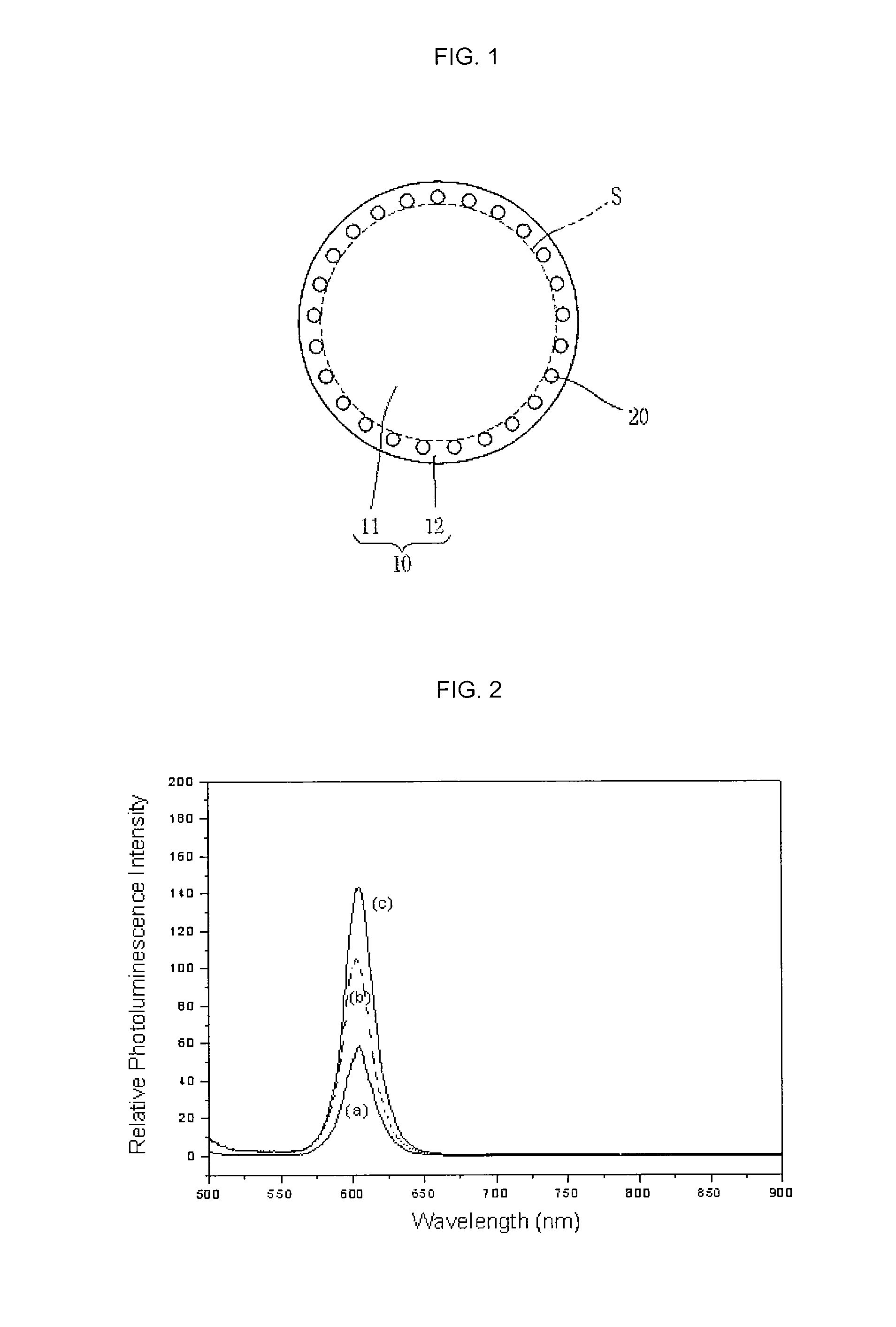
[0012]Therefore, to overcome the drawbacks of the related art, an object of the present invention is to provide a photoluminescent body capable of ensuring improved photo-stability, durability and enhanced fluorescence intensity without wavelength shift by allowing a monolayer of inorganic photoluminescent nanoparticles to be uniformly doped inside a porous bead near a surface thereof, without using an organic polymer, and a fabrication method thereof. More particularly, the present invention provides a doped bead simultaneously having photoluminescence properties and properties, such as magnetism, of another particles, by mixing photoluminescent nanoparticles together with another nanoparticles, such as magnetic nanoparticles, metallic nanoparticles or metallic oxide nanoparticles, and a fabrication method thereof.

Problems solved by technology

2004, 43, 5393-5396], the former caused the result that the final fluorescence intensity was rather decreased due to the self quenching between quantum dots located within different distances from the center of the bead, while the latter caused the result that the emitted fluorescence was extremely weakened because the quantum dot was doped deeply inside the silica bead.
However, in this case, because the amounts of charges of the surfaces of the silica beads and the nanoparticles were not sufficient, the electrostatic force was too weak to uniformly dope the nanoparticle layer on the surface of the silica beads.
Accordingly, once being bonded, the quantum dots cannot be relocated on the silica, which causes a non-uniform arrangement and generation of many empty spaces.
That is, the quantum dots of the quantum dot layer are non-uniformly and loosely distributed, resulting in insufficient fluorescence intensity, so a problem in usage may occur.
From our experience, this can be additionally interpreted as a situation that the available size of quantum dot is decreased due to oxidation proceeding on the surface of the quantum dot caused by the polycationic polymer doping, and it is difficult to constantly maintain or predict the size of blue shift for each reaction.
Further, since the thickness of the doped polymer layer is partially non-uniform, the quantum dots of the quantum dot layer are not uniformly distributed, resulting in the chance of weakening the fluorescence intensity.
In addition, in this report, since the polystyrene bead is an organic component, if it is used to make a device, for long-term use, such as laser or LED material, a problem in durability may occur.

Method used


Image

  • Nanoparticle-doped porous bead and fabrication method thereof
  • Nanoparticle-doped porous bead and fabrication method thereof
  • Nanoparticle-doped porous bead and fabrication method thereof

Examples


example 1

Fabrication of Silica Bead with Quantum Dot (Photoluminescent Nanoparticle) Layer Doped Therein

[0054](1) Fabrication of polyanionic monodispersed quantum dot CdSe / CdS(—SCH2CH2CO2−)ex aqueous solution

[0055]5 ml of quantum dot solution (2×10⁻⁵ M) in a core and shell structure (CdSe / CdS-ODA) with a surface protected by octadecylamine (ODA) was prepared and evaporates a hexane solvent therefrom by vacuum. The resultant solution was dispersed in 10 ml of chloroform, to which a methanol solution having 0.05 M mercaptopropionic acid (MPA) and 0.06 M sodium hydroxide melted therein, was then excessively added, thereafter being strongly stirred for 30 minutes. When 2 to 3 mL of distilled water was added to the stirred solution, quantum dots came up to a water layer, which was then separated. Methanol and ethylacetate were added into the separated water layer, thereby collecting the quantum dots by a centrifugal separation. Such quantum dots were dispersed in water and pH of the solution was ...

example 2

Fabrication of Silica Bead with Mixed Layer of Photoluminescent Nanoparticles and Another Nanoparticles Doped Therein

[0062](1) Fabrication of Polyanionic Monodispersed Iron Oxide Nanoparticle SPION (—O2CCH2CH2PO3−)ex aqueous solution

[0063]0.08 g of Trioctylammonium bromide was added to 10 mL of iron oxide nanoparticle (SPION-OA) solution having a surface protected by olein acid (OA) to be shaken for one day. To this solution was added 10 mL of solution containing 0.1 M carboxyethyl phosphonate, to thereby be shaken for another one day. When water and methanol were sequentially added to the resultant solution to be centrifugally separated, precipitates were generated. The precipitates were rinsed with ethanol and then centrifugally separated. Such precipitates were dispersed in water and pH of the solution was adjusted to approximately 10 by use of a diluted sodium hydroxide solution, thereby fabricating 190 mL (2×10⁻⁸ M) of polyanionic monodispersed nanoparticle (SPION(—O2CCH2CH2PO3...


PUM

PropertyMeasurementUnit
thicknessaaaaaaaaaa
sizeaaaaaaaaaa
thicknessaaaaaaaaaa

Abstract

Disclosed are a nanoparticle-doped porous bead with a highly enhanced photoluminescence without wavelength shift and improved durability, and a fabrication method thereof, the nanoparticle-doped porous bead comprising porous beads, and nanoparticles radially bonded onto homocentric spheres of the porous beads by an electrostatic attractive force, the homocentric sphere located inside the porous bead near a surface thereof, wherein the nanoparticles are photoluminescent nanoparticles or mixed nanoparticles of photoluminescent nanoparticles and another nanoparticles, wherein the another nanoparticle is one or more than two mixed, selected from a group consisting of magnetic nanoparticle, metallic nanoparticle and metal oxide nanoparticle.

Description

CROSS-REFERENCE TO A RELATED APPLICATION[0001]Pursuant to 35 U.S.C. §119(a), this application claims the benefit of earlier filing date and right of priority to Korean Applications No. 10-2009-0019456, filed on Mar. 6, 2009 and Korean Applications No. 10-2009-0059930, filed on Jul. 1, 2009, the content of which are incorporated by reference herein in its entirety.BACKGROUND OF THE INVENTION[0002]1. Field of the Invention[0003]The present invention relates to a nanoparticle-doped porous bead having an enhanced fluorescence intensity without wavelength shift, improved durability, and a fabrication method thereof.[0004]2. Background of the Invention[0005]Purcell expressed a theoretical predication in 1946 that if a luminous body is placed near the surface of a porous bead with a size of several tens nanometer to several tens micron, luminance intensity would be enhanced much higher than only the luminous body being used alone, due to a resonance coupling between the photons emitted fro...

Claims


Application Information

Patent Timeline
Patent Type & Authority Applications(United States)
IPC IPC(8): C09K11/54C09K11/77C09K11/08
CPCC09K11/02C09K11/025C09K11/565C09K11/642C09K11/7734C09K11/892C09K11/7741C09K11/7787C09K11/7789C09K11/883C09K11/7738
Inventor WOO, KYOUNGJACHO, MYUNGJE
Owner KOREA INST OF SCI & TECH
Why Eureka
Try Eureka