Nozzle member and process for producing the same

a technology of nozzles and parts, applied in the field of nozzle parts, can solve the problems of wasting material costs and huge resources on spinning nozzles, affecting the quality of nozzle parts, and damage to through hole forming pins by being bent or broken, etc., to achieve excellent performance, high precision and uniform formation, and the effect of reducing manufacturing costs

Active Publication Date: 2010-09-30
TOKYO ELECTRON LTD +1
View PDF9 Cites 35 Cited by
  • Summary
  • Abstract
  • Description
  • Claims
  • Application Information

AI Technical Summary

Benefits of technology

[0026]Since a diameter dimension of a through hole may be set from 10 μm to 100 μm, and a length (L) to diameter (D) ratio (L/D), i.e., an aspect ratio, of the through hole may be large, such as 5 or above, as the occasion commands, fluid stably flows in a laminar flow without turbulence, and thus a nozzle member has excellent performance for spinning, for a vacuum suction plate, for discharging or ejecting gas or liquid, and for other purposes.
[0027]According to a method of manufacturing a nozzle member of the present invention, the nozzle member including one or more minute and long through holes having a diameter dimension of 100 μm or lower and an aspect ratio of 5 or above, which is difficult to be manufactured by using a conventional method, may be manufactured by using an extrusion molding method or a cast molding method.
[0028]Since...

Problems solved by technology

However, when the discharge holes are directly formed in a nozzle body, the spinning nozzle is considered to be defective if just one discharge hole is defective.
Thus, material costs and huge resources spent on the spinning nozzle are wasted.
However, when a nozzle member including a plurality of through holes (minute holes) is manufactured by using an injection molding method or an extrusion molding method, wherein the injection molding or extrusion molding method is largely used as a simple and optimum method for forming a minute path including a discharge hole for a fluid, and a diameter of a through hole-forming pin (round rod) used in a mold is 0.2 mm (200 μm) or lower, or 0.1 mm (100 μm) or lower, the through hole-forming pin may be damaged by being bent or broken.
Accordingly, the through holes may be difficult to be manufactured.
Meanwhile, as an ideal nozzle characteristic, a fluid needs to be straightly discharged in a laminar flow when the fluid is discharged from a through hole of a nozzle member, because a problem may occur when the fluid is turbulently discharged.
However, when an injection molding method or an extrusion molding method is used to form a through hole having a diameter of 200 μm or less, in detail, 100 μm or less, and an aspect ratio of 5 or above, a through hole-forming pin used in a mold may be deformed or damaged.
Also, when a laser processing method is used, it is difficult to make a diameter of the through hole identical along the overall length of the through hole, and to polish the inner wall surface of the through hole.
Accordingly, the tool may often be deformed or damaged, and thus it is difficult to form the through hole.
Moreover, when the diameter of the through hole is 100 μm or less, it is very difficult to form the thr...

Method used


Image

  • Nozzle member and process for producing the same
  • Nozzle member and process for producing the same
  • Nozzle member and process for producing the same

Examples


example 1

[0040]First, a mixture is prepared by mixing 6 parts by mass of a binder for extrusion molding and 100 parts by mass of a raw material of ceramics for forming a nozzle member of a fluid nozzle in a mixer, and gradually adding a predetermined amount of water to the mixer, wherein the ceramics are alumina-based ceramics in which 0.4 mass % and 0.1 mass % of Al2O3 having 99.9% purity or above and an average particle size of 0.6 μm are respectively substituted by MgO and Y2O3, which are highly pure and fine powder particles.

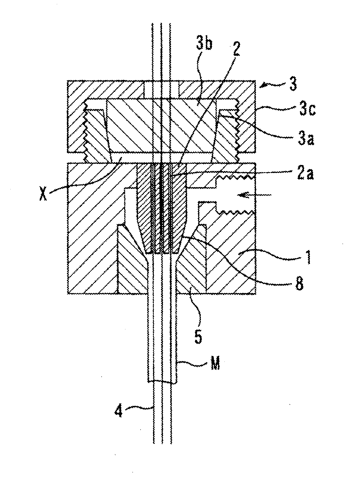
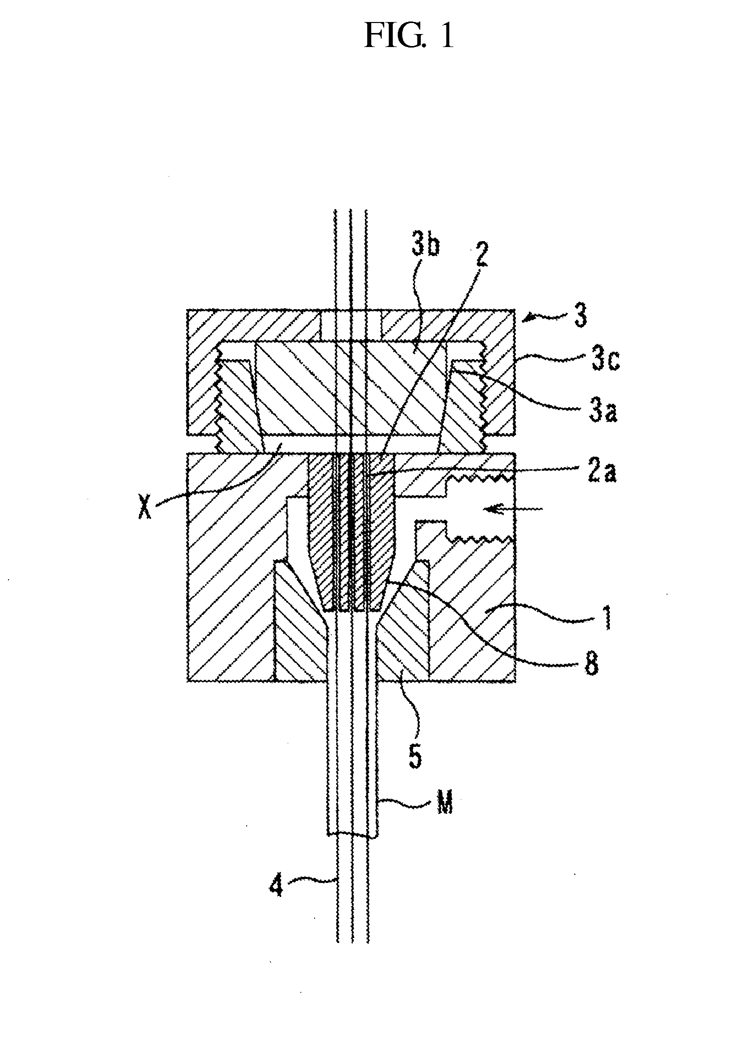
[0041]Meanwhile, seven guide holes 2a formed in a filament guide 2 installed at the center axis of a nozzle body 1 of a mold for extrusion molding illustrated in FIG. 1 are formed to have a dimensional tolerance within ±1 μm. A filament 4 formed of synthetic resin and having a diameter of 70 μm is drawn from a filament supplier 3 having a back-tension function. The filament 4 is inserted into and passed through each of the guide holes 2a. The filament 4 passes throug...

example 2

[0049]Mullite-based ceramic powder is prepared as a raw material of ceramics for forming the nozzle member, by performing a co-precipitation method on a mixed solution of an aluminum chloride solution and an ethyl silicate solution, in which Al2O3 is from 65 to 75 mass % and SiO2 is from 25 to 35 mass %.

[0050]Alternatively, a compound of Al2O3 and Y2O3 is prepared as the raw material of ceramics, by mixing 99 mass % of Al2O3 powder having 99.5% purity and an average particle size of 0.8 μm and 1 mass % of Y2O3 powder having 99.9% purity and an average particle size of 0.6 μm and 0.3 μm.

[0051]Alternatively, mixed powder is prepared as the raw material of ceramics, by substituting 5 mass % and 3 mass % of Al2O3 powder having 99.5% purity and an average particle size of 0.4 μm by ZrO2 powder partially stabilized with 2.5 mol % of Y2O3.

[0052]Alternatively, ZrO2-based ceramic powder is prepared as the raw material of ceramics, by preparing ZrO2 powder partially stabilized with 2.5 mol % ...

example 3

[0054]A slurry is prepared by pulverizing and mixing 100 parts by mass of Al2O3 powder having 99.99% purity or above and an average particle size of 0.5 μm, 100 L of water, 4 parts by mass of an emulsion type wax-based binder in solid content, 0.5 parts by mass of antifoaming agent, and 0.5 parts by mass of deflocculant by using is a ball mill.

[0055]In order to manufacture a nozzle member from the slurry via cast molding, a mold 9 for cast molding, formed of a porous resin as illustrated in FIG. 5 is used. According to the mold 9, a filament 11 formed of synthetic resin, carbon, a metal, or the like and having a diameter of 100 μm is inserted into and passed through each of seven narrow holes formed in a lower plate member 10 of the mold 9 without a gap, the filament 11 is disposed in a direction of an center axis of the mold 9, an absorption container 12 that is divided into halves is attached around a protruding portion 10a of the lower plate member 10, as a porous resin mold, wit...


PUM

PropertyMeasurementUnit
Lengthaaaaaaaaaa
Lengthaaaaaaaaaa
Fractionaaaaaaaaaa

Abstract

The nozzle member of a fluid nozzle includes at least one through hole that is parallel to a center axis, wherein a diameter dimension of the through hole is 10 μm to 100 μm, a length-to-diameter ratio (L/D) of the through hole is 5 or above, and the nozzle member is formed of ceramics having relative density of 95% or above. The nozzle member including a plurality of minute through holes is manufactured by performing extrusion or cast molding in such a way that a molded body includes a filament of synthetic resin, carbon, or metal in a direction of the center axis of the molded body, and then defatting/sintering the molded body after removing the filament or, when the filament is formed of synthetic resin or carbon, defatting/sintering the molded body under oxidizing atmosphere to evaporate and remove the filament without removing the filament from the molded body.

Description

TECHNICAL FIELD[0001]The present invention relates to a nozzle member of a fluid nozzle used to discharge, eject or vacuum-absorb a fluid, such as gas or liquid, and a method of producing the nozzle member.BACKGROUND ART[0002]In general, a nozzle member is used as a nozzle for discharging or ejecting a fluid, such as gas or liquid, from a plurality of discharge holes. In order to uniformly discharge or eject the fluid, a tolerance of a diameter dimension of a through hole constituting a fluid path of a nozzle member may be as small as possible, the through hole may be highly precisely formed, and roughness of an inner wall surface of the is through hole may be low.[0003]The through hole of the nozzle member may be a minute hole having a small diameter dimension, and the plurality of through holes may be formed in a direction of the center axis of the nozzle member.[0004]For example, according to Japanese Laid-Open Patent Publication No. hei 10-88416 (hereinafter, referred to as Refe...

Claims


Application Information

Patent Timeline
IPC IPC(8): A62C31/02C04B35/64
CPCB28B3/2645C04B35/106D01D4/025C04B35/111C04B35/119C04B35/185C04B35/76C04B2235/3206C04B2235/3225C04B2235/3246C04B2235/5445C04B2235/6021C04B2235/6027C04B2235/77C04B2235/96B28B7/18B28B21/52B28B7/342
Inventor OKESAKU, MASAHIROMIYAHARA, MICHITO
Owner TOKYO ELECTRON LTD
Why Eureka
Try Eureka