Anti-fouling coatings and articles coated therewith

a technology of anti-fouling coating and protective coating, which is applied in the direction of superimposed coating process, machines/engines, liquid fuel engines, etc., can solve the problems of affecting the performance of compressor blades or airfoils, and gas turbine compressor components become fouled with a mixture of hydrocarbons. , to achieve the effect of improving the protective coating of compressor components

Inactive Publication Date: 2010-09-30
GENERAL ELECTRIC CO
View PDF9 Cites 60 Cited by
  • Summary
  • Abstract
  • Description
  • Claims
  • Application Information

AI Technical Summary

Problems solved by technology

In some situations the air drawn into the engine has constituents that are corrosive and abrasive to the compressor blades and other such parts.
In addition, gas turbine compressor components become fouled with a mixture of hydrocarbon-based lubricating oil, carbonaceous soot, dirt, rust and other like components.
For example, compressor blades are susceptible to corrosion pitting along leading edge surfaces of blades resulting from accumulation of fouling particles that cause galvanic attack.
The fouling affects the performance of compressor blades or airfoils and reduces efficiency of the gas turbine.
Along with technical loses, fouling may further be responsible for some financial loses such as higher fuel consumption, low power generation, and unscheduled maintenance.
However, this injected water here may further exacerbate the corrosion problem.
Generally these systems entail introducing water droplets at the compressor inlet, with the result that blades of the compressor are impacted by water droplets at high velocities.
Compressor blades formed of iron-based alloys, including series 400 stainless steels, are prone to water droplet erosion at their leading edges, including their roots where the blade airfoil attaches to the blade platform.
Various metallic / ceramic coatings have been suggested and tried; none has qualified for technical or economic reasons.

Method used


Image

  • Anti-fouling coatings and articles coated therewith
  • Anti-fouling coatings and articles coated therewith

Examples


example 1

Solid Particle Erosion Test

[0033]Solid-particle erosion measurements were performed with an Airbrasive jet machine at about 25 degrees Celsius. Test conditions are given in Table 1 below. Each GTD-450 substrate was coated with a composite coating material or a nitride as listed in Table 3. Erosion rates were calculated as mass loss per unit time. Table 1 shows average particle erosion rate along with comparison with a few metal coatings and GTD-450 substrate without any coating. Zirconium nitride and titanium nitride coatings had very good erosion resistance, approximately 10 times better than uncoated GTD-450 substrate. A metal-polymer composite, TFE-Lok Chrome PTFE coating, showed slightly better erosion resistance than uncoated GTD-450 substrate.

TABLE 1Test conditions for solid particle erosion testNozzle0.026″ dia. SapphirePowder FeederPlasmadynePowder Feed Rate (grams / min) 5Powder TypeMinetec Quartz particlesAverage Particle Size50 micronsCarrier Gas Type matterAirCarrier Gas F...

example 2

Fouling Test

[0034]Each GTD-450 substrate was coated with a composite coating material or a nitride as listed in Table 3. The fouling test was conducted with a fouling rig creating a dynamic environment to simulate accelerated foulant and water wash. The rig contained a blow down wind tunnel with a test cross-section that created flow speeds of up to 0.7 Mach. The samples were developed from a ⅓rd scale inlet guide vane (IGV) section. Five samples were arranged 1 inch apart such that the throat ratio in the sample configuration was the same as that in a typical turbine compressor. With this sample arrangement in the test section, the wind tunnel was calibrated to achieve 0.4 Mach, which was the set flow speed for all tests conducted. The foulants chosen were a mixture of Mobil DTE 832 gas turbine lube oil with 0.25% carbon black. Carbon black was added to mimic particulate layer formation on oil films.

[0035]The fouling tests were divided into four stages: (I) oil flow, (II) aero impa...

example 3

Corrosion Resistance Test

[0036]Corrosion resistance measurements were performed with a potentiostat. About 1 cm2 of intact coating was externally coupled electrically to a small area of a polished GTD-450 pin (edge of the pin) embedded in an epoxy matrix. The system was immersed in 5% chloride medium at 50 degrees Celsius. The galvanic current and potential were measured by the potentiostat over about 48 hr time period.

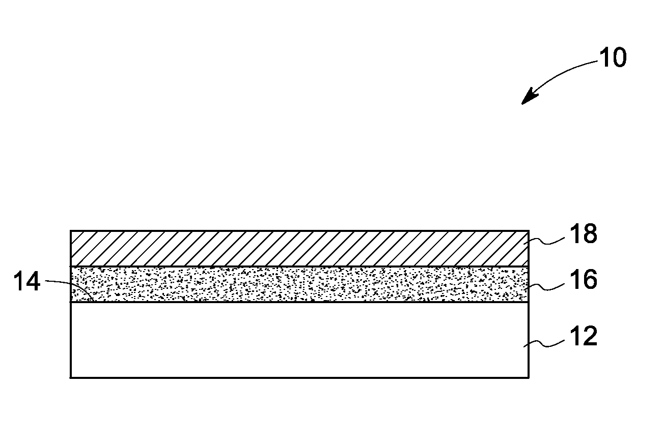
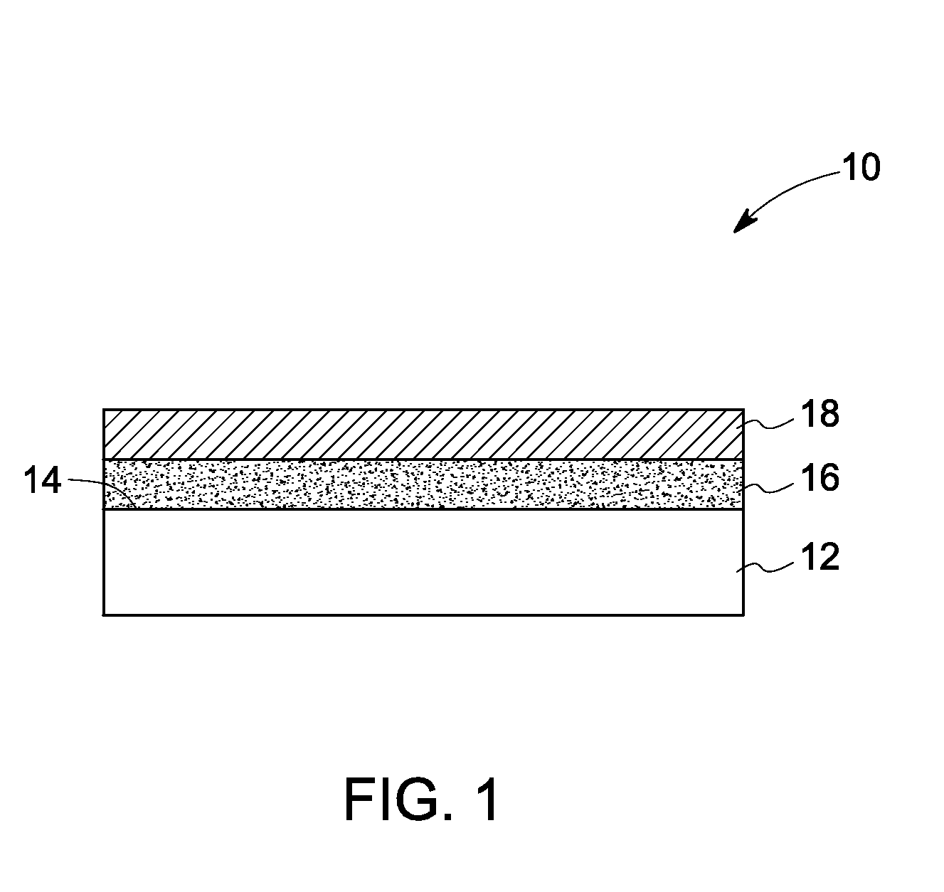
[0037]Three samples of coating-substrate systems were developed for measurements. The first sample was a GTD-450 substrate coated with titanium nitride (TiN) coating. The second sample had an aluminum layer applied by High-Velocity Air Fuel spraying (HVAF) deposition technique over a GTD-450 substrate. The third sample was prepared by coating a titanium nitride layer over an aluminum layer similar to the second sample. The samples were polished to less than 1-micron average roughness. The TiN coating was subsequently deposited by physical vapor deposition (PVD).

[0038]...


PUM

PropertyMeasurementUnit
volume percentaaaaaaaaaa
temperaturesaaaaaaaaaa
thicknessesaaaaaaaaaa

Abstract

An article including a metallic substrate is presented. The article further includes a sacrificial layer disposed on a surface of the substrate and an anti-fouling layer disposed on the sacrificial layer. The anti-fouling layer includes a metal-polymer composite. An article including an anti-fouling layer having a nitride is also presented.

Description

CROSS REFERENCE TO RELATED APPLICATIONS[0001]This application is a continuation in part of U.S. patent application Ser. No. 11 / 970,604, entitled “EROSION AND CORROSION-RESISTANT COATING SYSTEM AND PROCESS THEREFOR,” filed on Jan. 8, 2008, which is herein incorporated by reference.BACKGROUND[0002]The invention relates generally to protective coatings for turbine components. More particularly, the invention relates to a protective coating for gas turbine compressor components, and components that include such coatings.[0003]Components of industrial and marine gas turbines are subjected in normal use to a variety of operating conditions, particularly with respect to the ambient atmosphere. In some situations the air drawn into the engine has constituents that are corrosive and abrasive to the compressor blades and other such parts. Corrosion is exacerbated if the turbine operates in or near a corrosive environment, such as near a chemical or petroleum plant or near a body of saltwater....

Claims


Application Information

Patent Timeline
Patent Type & Authority Applications(United States)
IPC IPC(8): F01D5/14B32B15/04B32B15/08
CPCC23C4/08Y10T428/12569C23C14/025C23C14/0641C23C30/00F01D5/286F01D5/288F04D29/026F05D2260/95F05D2300/43F05D2300/21C23C28/321C23C28/322C23C28/3225C23C28/324C23C28/345C23C28/347C23C4/18F04D29/023F05D2260/607F05D2300/20F05D2300/603F05D2300/611Y10T428/31678
Inventor KULKARNI, AMBARISH JAYANTHALL, DAVID BRUCERUUD, JAMES ANTHONYSUNDARARAJAN, GURUPRASADZHONG, DALONG
Owner GENERAL ELECTRIC CO
Why Eureka
Try Eureka