
Metal composite substrate and method of producing the same

a composite substrate and metal technology, applied in the direction of superimposed coating process, semiconductor/solid-state device details, transportation and packaging, etc., can solve the problems of difficult handling at high temperatures, difficult to dispose of such glass substrates in a curved shape, and difficult to achieve consistent production, good flatness, and high efficiency

Inactive Publication Date: 2010-11-04
FUJIFILM CORP
View PDF9 Cites 15 Cited by
  • Summary
  • Abstract
  • Description
  • Claims
  • Application Information

AI Technical Summary

Benefits of technology

[0021]The present invention provides a support or substrate obtained by anodizing a composite metal support having the entire surface coated with aluminum by hot dipping or the like, as the material which is suitable for use as a semiconductor material such as a thin-film solar cell substrate, has high strength at elevated temperatures, and particularly maintains good flatness and withstands handling at high temperatures. It has been thus found that a lithographic printing plate support which has good surface hardness and good adhesion to the image recording layer and does not cause the reduction of the support strength or flatness even under the high temperature burning treatment, and an insulating substrate for semiconductor devices which has high insulating performance and high strength at elevated temperatures, and is excellent in the handleability at elevated temperatures and in the flatness after high-temperature heat treatment are obtained. The present invention has been thus completed.
[0022]An object of the present invention is to provide a composite substrate which has an anodized surface film-bearing aluminum or aluminum alloy layer and which exhibits high strength at elevated temperatures and excellent withstand voltage characteristics. Another object of the present invention is to provide a method of producing the composite substrate.
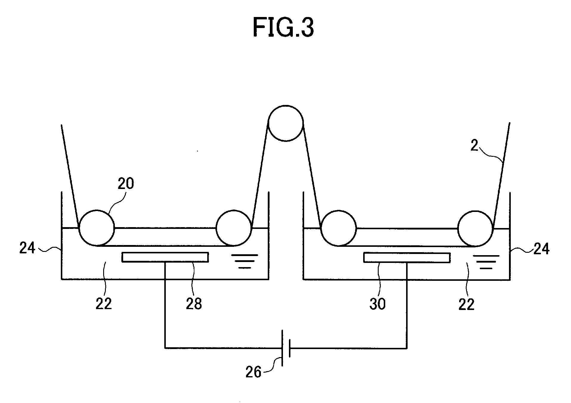
[0024]The composite substrate having a surface layer of aluminum or an aluminum alloy according to the present invention is one which has an anodized surface film and has good flatness during the high-temperature heat treatment. The metal composite substrate of the present invention can be used to manufacture with high efficiency, by a roll-to-roll process, a lithographic printing plate which withstands high-temperature burning treatment and an insulating flexible support for use in a solar cell substrate which withstands vapor deposition under high temperatures.
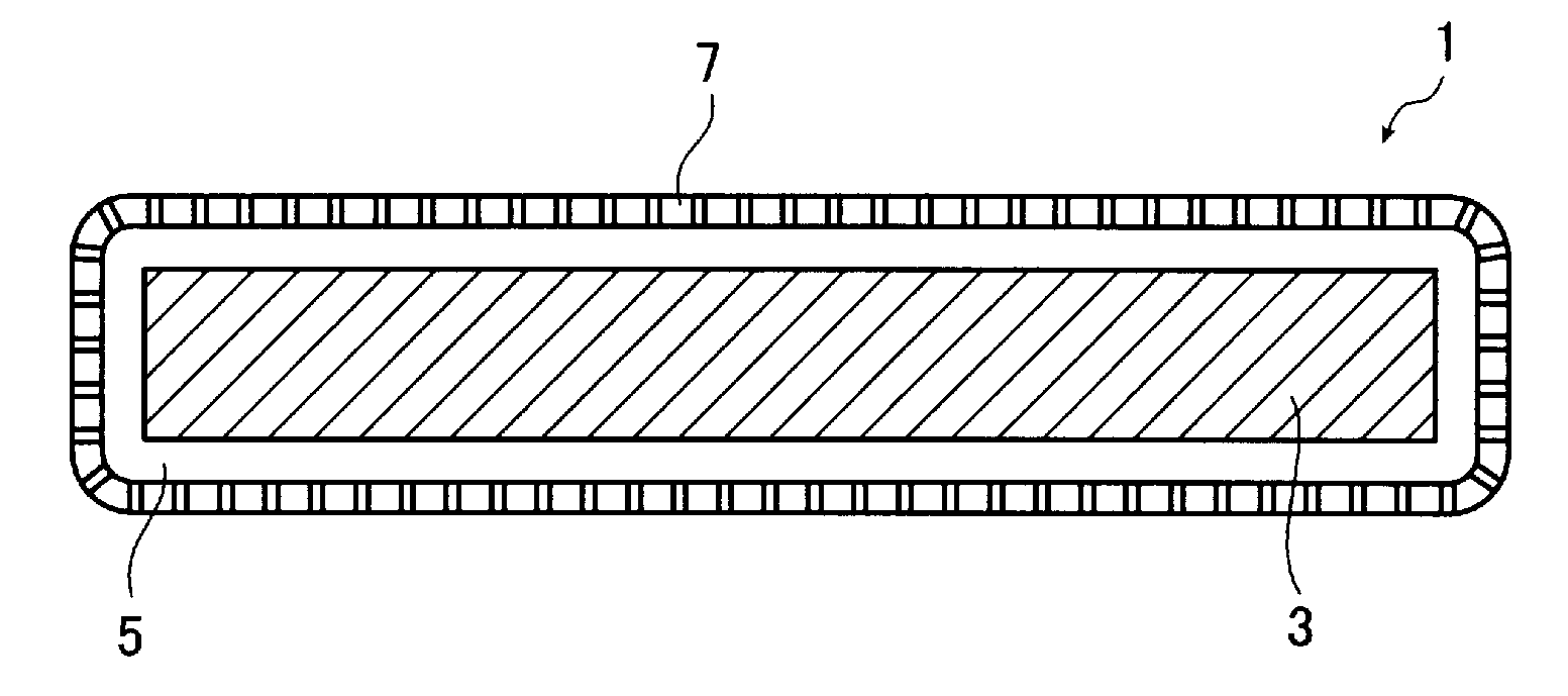
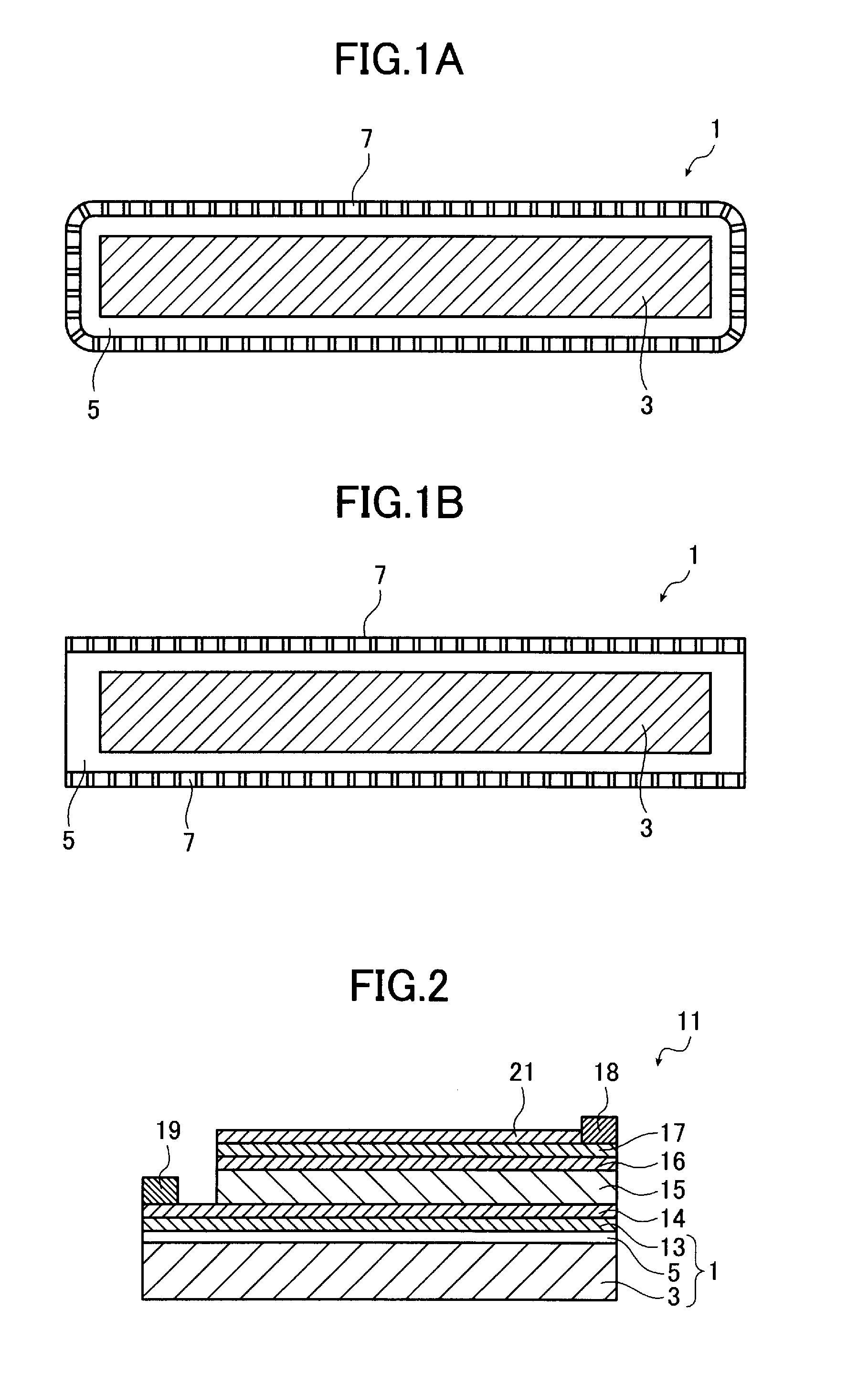
[0025]The metal composite substrate of the present invention has the core entirely coated with aluminum or an aluminum alloy and therefore has the advantage that the material of the core or the contact surface does not dissolve compared to the substrate which has only one surface or two main surfaces covered with aluminum or an aluminum alloy and in which the material of the core or the contact surface dissolves from the end portions where the contact surface between the core and the aluminum layer is exposed during the anodized film-forming step carried out in the electrolytic solution. On the other hand, in order to avoid this defect by using a substrate which has one surface or two main surfaces comprising aluminum or an aluminum alloy, a preliminary step for preventing end surfaces from contacting the electrolytic solution is necessary. More specifically, a step for covering the end surfaces with a protective material having excellent chemical resistance is necessary. In cases where the end surfaces are covered with a protective material, the end portions are more likely to have a larger thickness due to the protective material used, and consequently there is a high possibility that breakage will occur during the handling of the substrate which is made to travel while contacting the pass rolls. In cases where the protective material does not sufficiently adhere to the end surfaces, the electrolytic solution is more likely to enter the gap to cause dissolution at the end surfaces. The inventive method can avoid these defects. In cases where the end surfaces must also have insulating properties, the anodized film formed via the aluminum or aluminum alloy layer with which the end surfaces are covered also ensures the insulating properties of the end surfaces. The anodized film formed via the aluminum or aluminum alloy layer with which the end surfaces are also covered has the effect of protecting the end surfaces against corrosion and dissolution in cases where chemical treatment is carried out in a step following anodizing treatment.

Problems solved by technology

However, it is difficult to dispose such glass substrates in a curved shape for lack of flexibility and methods of providing a metal substrate have been proposed as in JP 2007-502536 A, JP 11-229187 A, JP 2000-49372 A, JP 11-97724A and JP 2000-286432 A. However, in cases where thin-film solar cells which require formation of a light-absorbing layer at high temperatures are to be produced, handling at high temperatures and hence their consistent production are difficult because a substrate which uses an aluminum film having an insulating anodized surface layer as described in JP 11-229187 A, JP 2000-49372 A, JP 11-97724 A, and JP 2000-286432 A has difficulty in holding the shape for lack of strength at high temperatures.
A method of providing an insulating layer in a steel product as described in JP 2007-502536 A has also been proposed but the insulating performance is not sufficient and no power generation voltage can be obtained by connecting solar cells in series on substrates.
High-strength aluminum alloys as in JP 2008-81794 A have also been proposed, but it is difficult to form a light-absorbing layer at a temperature of as high as 500° C. or more and particularly flatness cannot be held.
In addition, iron and manganese added to the aluminum metal easily produce intermetallic compounds, consequently leading to the fatal outcome that the intermetallic compounds cause a defect of the anodized film formed at the aluminum metal surface to reduce the insulating resistance.

Method used


Image

  • Metal composite substrate and method of producing the same
  • Metal composite substrate and method of producing the same
  • Metal composite substrate and method of producing the same

Examples


examples

[0092]The present invention is described below by way of examples and comparative examples. However, the present invention should not be construed as being limited to the following examples. Unless otherwise specified, the percentages shown in Examples are expressed by weight.

[0093]Metallic materials (a stainless steel and steels) with a thickness of 100 μm were used for the core and the core was entirely coated with an aluminum alloy (aluminum purity: 99.9%) to a thickness of 70 μm by hot dipping.

[0094]As shown in Table 1, a stainless steel SUS304 was used for the cores in Examples 1 and 2, a heat resisting steel SUH309 for the cores in Examples 3 and 4, and a mild steel SS400 for the cores in Examples 5 and 6. The cores were passed through molten aluminum with an aluminum purity of 99.9% to which no elements were added, thereby forming composite materials with a thickness of 240 μm.

[0095]For comparison, an aluminum alloy, a stainless steel, a heat resisting steel and a mild steel ...


PUM

PropertyMeasurementUnit
temperaturesaaaaaaaaaa
thicknessaaaaaaaaaa
thicknessaaaaaaaaaa

Abstract

A metal composite substrate includes a core made of a metal having higher strength than aluminum at elevated temperatures of at least 300° C. and an aluminum or aluminum alloy layer covering an entire surface of the core, and an anodized film is formed at a surface of the aluminum or aluminum alloy layer. The metal composite substrate having the anodized surface film can produce with high efficiency an insulating flexible support by a roll-to-roll process and has good flatness during the high-temperature heat treatment.

Description

TECHNICAL FIELD[0001]The present invention relates to a metal composite substrate. More specifically, the present invention relates to a metal composite substrate which has front and rear surfaces covered with an anodized aluminum alloy and which exhibits excellent strength properties at high temperatures.[0002]The semiconductor substrate is required to have high insulating properties and heat dissipation properties. The semiconductor substrate preferably also has high flexibility. In cases where an aluminum alloy is used for the semiconductor substrate, the aluminum alloy which is a material having high electrical conductivity cannot satisfy the required insulating properties when used as it is, but the insulating properties are drastically improved by providing an anodized surface layer. The aluminum alloy is a material having a good thermal conductivity and has therefore excellent heat dissipation properties and also has good flexibility by selecting an adequate plate thickness. ...

Claims


Application Information

Patent Timeline
Patent Type & Authority Applications(United States)
IPC IPC(8): H01L31/00B32B15/01B32B15/10B32B5/18C23C28/00H01L29/12
CPCC22C1/002H01L27/142H01L31/02Y10T428/12757Y10T428/12479Y10T428/12736Y02E10/50C22C1/11
Inventor SAWADA, HIROKAZUUESUGI, AKIO
Owner FUJIFILM CORP
Learn More