
Chemical modification process for a deep polymeric matrix

Inactive Publication Date: 2010-12-09
COMMISSARIAT A LENERGIE ATOMIQUE ET AUX ENERGIES ALTERNATIVES
View PDF16 Cites 4 Cited by
  • Summary
  • Abstract
  • Description
  • Claims
  • Application Information

AI Technical Summary

Benefits of technology

[0026]More particularly, the inventors have shown that the irradiation of certain polymer matrices via UV radiation having a certain wavelength make it possible to obtain, within the thickness of said matrix, activated zones which may participate in a radical grafting and / or be chemically developed or hollowed out.
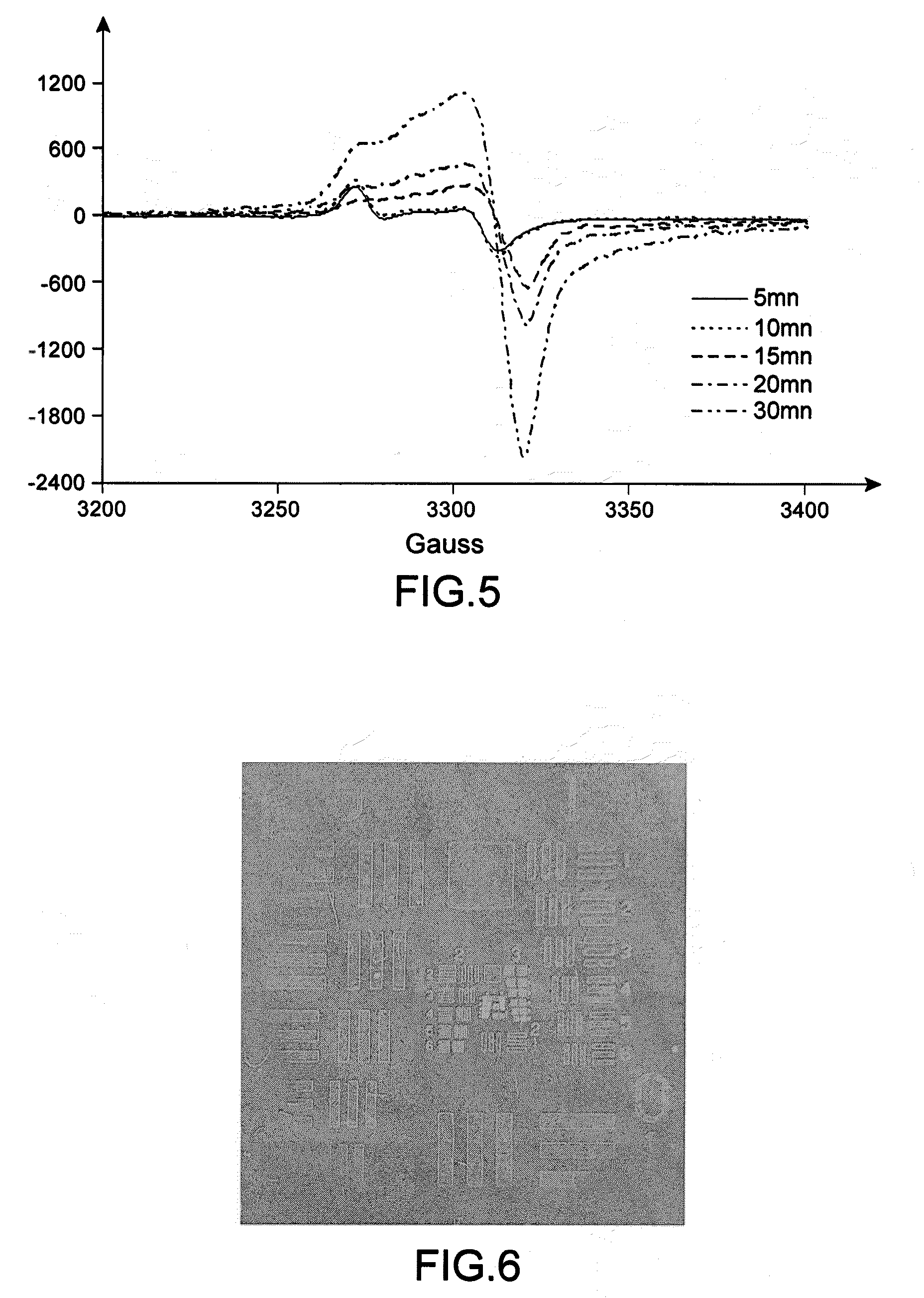
[0062]A second technique enabling such structuring consists in carrying out the irradiation step in the presence of a mask. The term “mask” is understood to mean a material that absorbs the UV radiation present at the surface of the polymer matrix and that partly covers it, without being grafted or covalently bonded to the latter. This material consequently makes it possible to “mask” a given volume from the UV radiation and thus to prevent, in this volume, the formation of free radicals following the irradiation and therefore the developing or grafting of compounds bearing an ethylenically unsaturated group. A person skilled in the art knows various materials that can be used as a mask such as materials made of silica, of resin, of Cr, of TaN, or materials used in extreme UV lithography. The use of such a mask makes it possible to create, within the volume of the polymer matrix, a 3D “patterning”, especially by creating hollowed out “channels” or “channels” of grafted polymers, when said mask is associated with a UV irradiation generated by a laser.
[0070]In a second variant, the irradiation step is carried out under an inert gas such as argon or under a neutral gas such as nitrogen. The irradiation under nitrogen or under an inert gas makes it possible to generate only radicals of alkyl type and to thus limit the presence of peroxide radicals. In this variant, prior to the irradiation step of the process according to the present invention, the chamber in which the polymer matrix made of fluoropolymers or of aliphatic polymers is found and in which the irradiation will be carried out may be subjected to a stream of nitrogen for a duration between 5 min and 3 h, especially between 15 min and 1 h and, in particular, of the order of 30 min. The expression “of the order of 30 min” is understood to mean a duration of 30 min±10 min. In this way, the chamber is purged and thus the presence of oxygen in the irradiation chamber is avoided.
[0092]Prior to the contacting of the solution (S) with the irradiated polymer matrix and / or from this contacting onwards, the solution (S) may be subjected to a sparging under nitrogen. The nitrogen sparging makes it possible to remove the molecular oxygen present in the solution. Indeed, since oxygen is known to be a radical reaction inhibitor, it is therefore very advantageous to remove it in order to increase the yield of the reaction.
[0107]The chemically modified polymer matrix obtained according to the process of the invention has the same uses and applications as any chemically modified polymer matrix and especially as the polymer matrices that are chemically modified at the surface. Mention may be made of a use for improving the metal / polymer matrix adhesion, a use as a proton-conducting membrane of a fuel cell, as supersorbents, filters or compresses by virtue of the improved retention of solutions or of particular chemical compounds, as biocompatible coatings, as battery separators, etc. As the chemical modification of the polymer matrix according to the present invention is not limited to the surface of the latter, it has the additional advantage with respect to the matrices of the prior art that the properties and characteristics due to the radiochemical grafting are maintained even if the surface of the polymer matrix is damaged.

Problems solved by technology

These techniques can only be implemented using heavy and expensive equipment.
On the other hand, it is clear for a person skilled in the art, by virtue of the abundant prior art at his disposal, that the radical grafting within the depth of a polymer matrix cannot be obtained by irradiating the latter with UV radiation.

Method used


Image

  • Chemical modification process for a deep polymeric matrix
  • Chemical modification process for a deep polymeric matrix
  • Chemical modification process for a deep polymeric matrix

Examples


Embodiment Construction

A. Materials and Methods

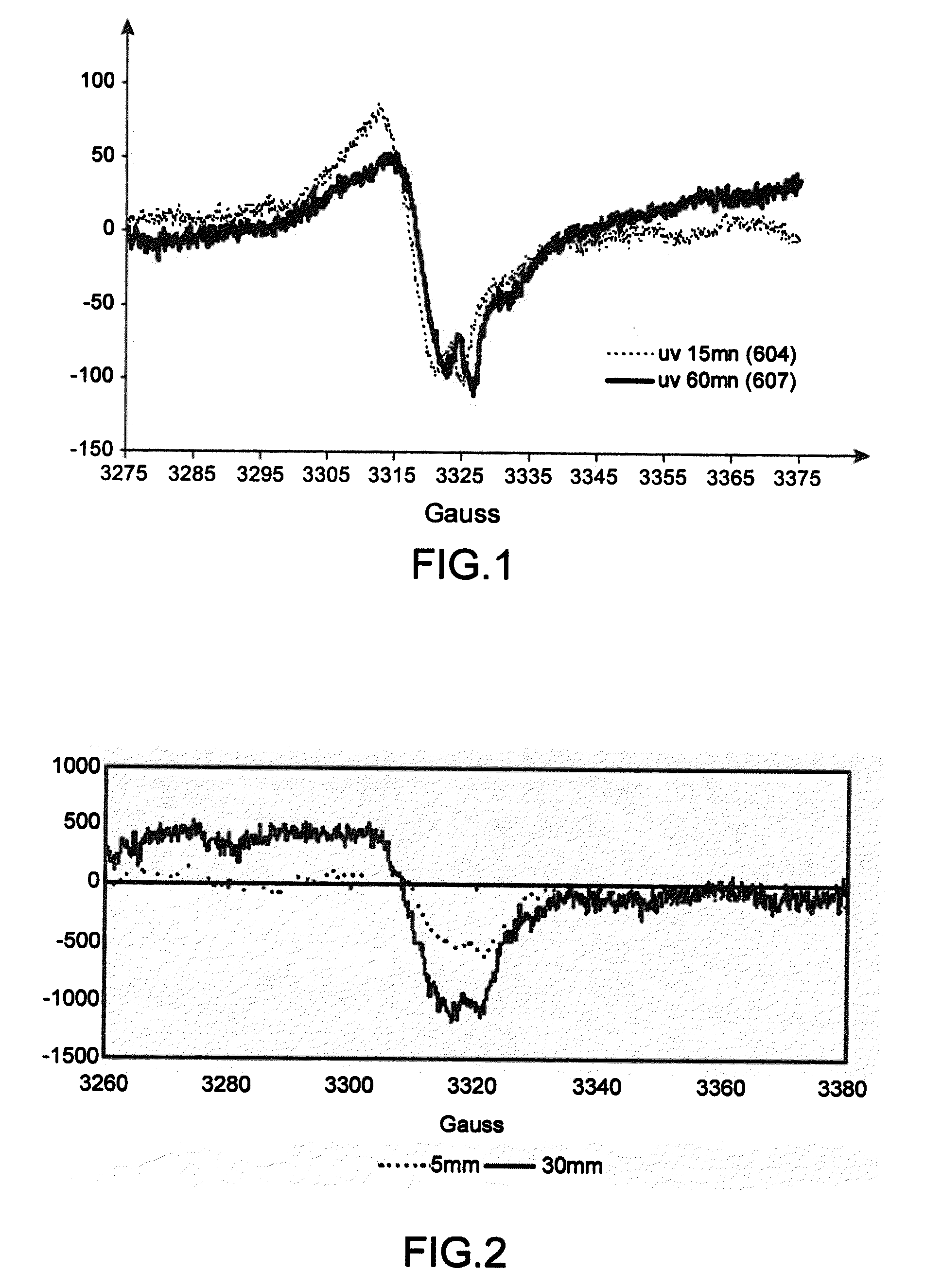
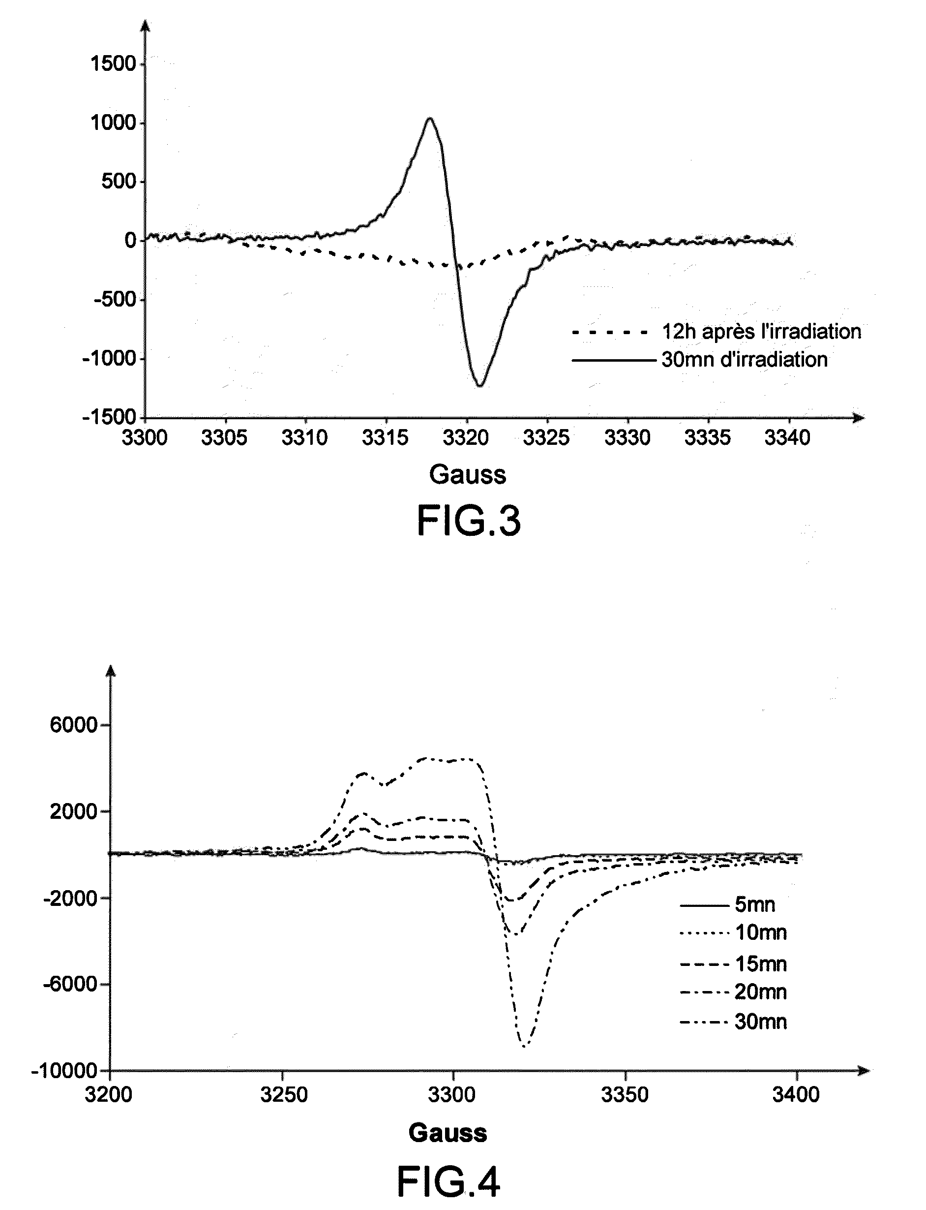
[0125]EPR: The EPR spectra are obtained with an X-band Bruker ESP300E machine operating at a frequency of 9.420 GHz at ambient temperature with a field modulation of 100 kHz and an amplitude modulation of 3 Gauss. All the spectra are normalized to a 100 mg sample and for a gain of 10 E4.

[0126]Laser: The laser irradiations are carried out with an INDI Nd:YAG pulsed laser (Spectra Physics) operating at 266 nm. The duration of each pulse is 8 ns and the pulse repetition frequency is 10 Hz. The final diameter of the laser beam is 8 mm and the energy delivered per pulse is of the order of 2 mJ.

[0127]V-UV: The samples are irradiated using a xenon excimer lamp, the power of which over the whole of the surface is 15 W. The V-UV light has a pulse repetition frequency of 30 kHz and the duration of each pulse is 4 μs.

[0128]UV: The Omnicure Series 2000 lamp is used to irradiate the samples with UV radiation. Having a total power of 200 W, it emits from 320 to 500 nm. It ...


PUM

PropertyMeasurementUnit
Thicknessaaaaaaaaaa
Wavelengthaaaaaaaaaa
Fractionaaaaaaaaaa

Abstract

The present invention relates to a process for chemically modifying, within its thickness, a polymer matrix chosen from matrices made of fluoropolymers and matrices made of aliphatic polymers, said process comprising at least one step consisting in irradiating said matrix with UV light having a wavelength of less than 300 nm in order to generate, within the thickness of said matrix, zones that have short polymer chains, formed by scission of the existing chains during the passage of the UV radiation and that have free radicals denoted hereinbelow as “activated zones”. The present invention also relates to the polymer matrix capable of being chemically modified by such a process.

Description

TECHNICAL FIELD[0001]The present invention relates to the field of polymer materials.[0002]More particularly, the present invention proposes a process that makes it possible to chemically modify a polymer material in depth, i.e. within the thickness of the material, in particular in order to modify the properties and the characteristics thereof. This chemical modification consists in creating activated zones within the thickness of the polymer which may, subsequently, either allow a radical grafting of an ethylenically unsaturated compound and / or of repeating units derived from such a compound, or be developed or hollowed out.PRIOR ART[0003]The chemical modification of the polymers has a large number of applications which include the recyclability of polymers, the crosslinking of polymers and the grafting to polymers that makes it possible to give them novel properties and features such as biocompatibility, metallization, adhesiveness, wettability or antifouling. The chemical modifi...

Claims


Application Information

Patent Timeline
IPC IPC(8): C08F2/46C08F14/22C08F10/02C08F22/10
CPCC08J3/28C08J7/123C08J7/16C08J2323/26C08J2327/18Y10T428/1352C23C18/18C23C18/1844C23C18/1893C23C18/2086C23C18/1601C08J7/18C08L27/12C23C18/16
Inventor BERTHELOT, THOMASBAUDIN, CECILE
Owner COMMISSARIAT A LENERGIE ATOMIQUE ET AUX ENERGIES ALTERNATIVES
Learn More