
Air electrode

a technology of air electrode and positive electrode, which is applied in the direction of fuel and primary cells, cell components, electrochemical generators, etc., can solve the problems of reducing the performance of fuel cells, air cannot be supplied to the positive electrode side, and alkaline fuel cells have not been made available for consumer applications, etc., to achieve excellent activity and avoid leakage of aqueous alkaline solution

Inactive Publication Date: 2010-12-23
NAT INST OF ADVANCED IND SCI & TECH
View PDF8 Cites 42 Cited by
  • Summary
  • Abstract
  • Description
  • Claims
  • Application Information

AI Technical Summary

Benefits of technology

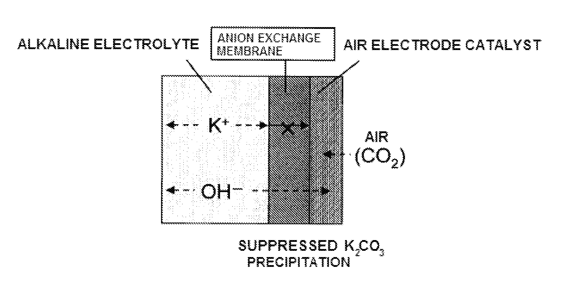
[0075]As described above, the air electrode of the present invention is characterized by providing an anion exchange membrane at the interface between the air electrode catalyst layer and the aqueous alkaline solution. Accordingly, astable air electrode performance can be maintained for a long period of time, and leakage of aqueous alkaline solution can be avoided. Consequently, safe and user-friendly metal-air batteries, alkaline fuel cells, and the like can be provided. Further, the air electrode of the present invention can also maintain excellent activity for the oxygen evolution reaction. This enables practical application of a metal-air secondary battery, and the use of an alkaline fuel cell as a water electrolysis device.
[0076]As described above, the air electrode of the present invention can solve or reduce various problems of conventional air electrodes, and is suitable as an air electrode for a metal-air battery, an alkaline fuel cell, and the like. A metal-air battery or alkaline fuel cell that uses the air electrode of the present invention is an extremely useful power source for various applications such as: small power sources for portable devices (mobile devices and IT devices), power sources for small transport means (scooters and electric wheelchairs), batteries for vehicles (hybrid vehicles and electric vehicles), and the like. Further, the air electrode can also be effectively used as a reversible electrode for a metal-air secondary battery and as an oxygen evolution electrode for an alkaline water electrolysis device.

Problems solved by technology

The lifetime of the battery is about 2 months because it is susceptible to humidity and carbon dioxide in the atmosphere.
However, in alkaline fuel cells, the alkaline electrolyte reacts with carbon dioxide in the atmosphere and turns into carbonate, causing a reduction in the fuel cell performance; accordingly, only pure hydrogen and pure oxygen can be used therein, and air cannot be supplied to the positive electrode side.
For this reason, alkaline fuel cells have not been made available for consumer applications.
However, such conventional air electrodes will have various problems during long-term use for the reasons described below.
When this carbonate is deposited in fine pores in the air electrode, air diffusion will be prevented, thus causing a decrease in the air electrode performance.
Further, when the aqueous alkaline solution gradually permeates into the air electrode, the concentration overvoltage will increase, and the solution will leak, along with an increase in the wetting of the air electrode.
However, carbonate deposition caused by carbon dioxide in the atmosphere and leakage of the alkaline electrolyte cannot be completely prevented by the above-described methods, and measures for further improvement are needed.
Further, the methods as described in Patent Document 1 and Non-Patent Document 1 require the installation of a carbon dioxide removing device in addition to the battery itself; these methods are thus not suitable for batteries for mobile applications, in which a reduction in the size and weight is required.
As described above, although the expansion of practical application and spread of metal-air batteries and alkaline fuel cells have been expected, the current situation is such that there are many problems arising from the use of an aqueous alkaline solution as the electrolyte, and many issues need to be improved.Patent Document 1: Japanese Unexamined Patent Publication No. 49-49128Patent Document 2: Japanese Unexamined Patent Publication No. 2000-3735Patent Document 3: Japanese Unexamined Patent Publication No. 53-51448Patent Document 4: Japanese Unexamined Patent Publication No. 62-69472Patent Document 5: Japanese Unexamined Patent Publication No. 2005-235485Non-Patent Document 1: Phys. Chem. Chem. Phys., 3, 368 (2001)

Method used


Image

  • Air electrode
  • Air electrode

Examples


example 1

[0080]Platinum black was used as an air electrode catalyst. The platinum black was mixed with a polytetrafluoroethylene dispersion liquid having a concentration of 60 wt % and ethanol such that the ratio (weight ratio) of platinum black:polytetrafluoroethylene dispersion liquid:ethanol=5:1:1, thus obtaining a catalyst ink. The catalyst ink was applied onto a carbon cloth such that the amount of deposited platinum was 3 mg / cm2, and then dried by heating, thus obtaining an air electrode catalyst layer.

[0081]As the anion exchange membrane, a 27 μm-thick hydrocarbon membrane having an ion exchange capacity of 1.4 mmol / g and containing a quaternary ammonium group as an ion exchange group was used. The above-described air electrode catalyst layer was hot-pressed onto one side of the membrane and integrated therewith.

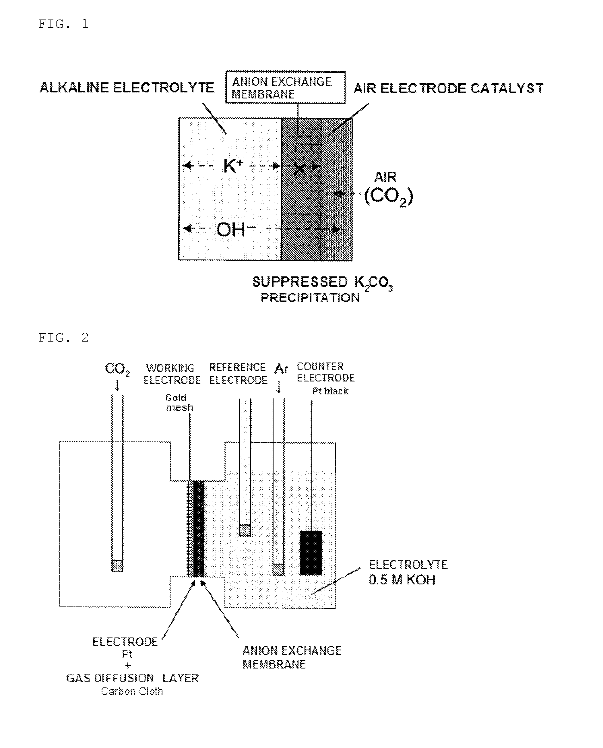
[0082]Using the thus-obtained air electrode, an H-shaped cell, shown in a schematic view in FIG. 2, was prepared according to the following method, and an evaluation test on t...

example 2

[0089]Platinum black that was treated with polytetrafluoroethylene to give water-repellency was used as an air electrode catalyst. This platinum black catalyst was mixed with a 5 wt % solution of anion exchange resin (hydrocarbon-based resin with an ion exchange capacity of 2 mmol / g, which contains a quaternary ammonium group as an ion exchange group) and ethanol such that the ratio (weight ratio) of platinum black:anion exchange resin solution:ethanol=1:2.2:2, thus obtaining a catalyst ink. The catalyst ink was formed into a thin membrane to prepare an air electrode catalyst layer.

[0090]As the anion exchange membrane, a 27 μm-thick hydrocarbon membrane having an ion exchange capacity of 1.4 mmol / g and containing a quaternary ammonium group as an ion exchange group was used. The air electrode catalyst layer obtained according to the above method was hot-pressed onto one side of the membrane, and integrated therewith. The amount of platinum catalyst was 3 mg / cm2, the anion exchange r...

example 3

[0095]An air electrode integrated with the anion exchange membrane was prepared by the same method as in Example 1. This air electrode was inserted into an H-shaped cell shown in FIG. 2, and the oxygen reduction property in the air electrode was evaluated by three-electrode measurements in the same manner as in Example 1.

[0096]After measuring the initial value of the oxygen reduction current in the air electrode, carbon dioxide was supplied to the air electrode catalyst layer side at a flow rate of 100 mL / min for one hour. Then, the air electrode catalyst layer side was again open to the atmosphere, and the oxygen reduction current was measured. This operation was repeated four times, and carbon dioxide was thereby supplied for a total of four hours. Then, the influence of carbon dioxide on the oxygen reduction property was observed.

[0097]Table 3 shows how the ratio (it / i0×100(%)) between the initial value (i0) of the oxygen reduction current at a potential of 0.6 V versus RHE and t...


PUM


Abstract

Provided are an air electrode having a structure in which an anion exchange membrane and an air electrode catalyst layer are laminated and the anion exchange membrane is disposed in contact with an aqueous alkaline solution; and a metal-air battery, an alkaline fuel cell, and a water electrolysis device each having the air electrode. The air electrode of the present invention can reduce or solve various conventional problems of an air electrode in a metal-air battery, fuel cell, and the like, which use an aqueous alkaline solution as an electrolyte, and can maintain high performance for a long period of time.

Description

TECHNICAL FIELD[0001]The present invention relates to an air electrode having a novel structure and its use, the air electrode being useful as an air electrode having a function to reduce oxygen in a metal-air battery using an alkaline electrolyte, an alkaline fuel cell, or the like; and as an air electrode having a function to evolve oxygen in a metal-air secondary battery, an alkaline water electrolysis device, or the like.BACKGROUND ART[0002]A metal-air battery is a battery that uses a metal such as zinc, aluminum, magnesium, or the like as a negative electrode, and an air electrode as a positive electrode. In a metal-air battery, when the anode metal is zinc, the discharge reaction of the battery is represented as follows:Positive electrode (air electrode): O2+2H2O+4e−→4OH−Negative electrode (metal electrode): Zn+2OH→ZnO+H2O+2eTotal reaction: Zn+½O2→ZnO[0003]In the above reaction, oxygen is supplied from outside air, and used as a positive electrode active material. The air elec...

Claims


Application Information

Patent Timeline
Patent Type & Authority Applications(United States)
IPC IPC(8): H01M8/22H01M4/02H01M6/04C25B11/03C25B9/06C25B9/17C25B9/23
CPCC25B9/10H01M4/8605Y02E60/50H01M12/06H01M2004/8689H01M8/083C25B9/23
Inventor FUJIWARA, NAOKOYASUDA, KAZUAKIIOROI, TSUTOMU
Owner NAT INST OF ADVANCED IND SCI & TECH
Learn More