Carbon catalyst, slurry containing the carbon catalyst, process for producing carbon catalyst, and fuel cell, storage device, and environmental catalyst each employing carbon catalyst

a technology of carbon catalyst and carbon slurry, which is applied in the direction of catalyst activation/preparation, metal/metal-oxide/metal-hydroxide catalyst, etc., to achieve the effect of prolonging the service life of the electric storage device, reducing the volume of the fuel cell, and increasing the electric storage capacity per unit volum

Inactive Publication Date: 2010-12-23
GUNMA UNIVERSITY +1
View PDF4 Cites 42 Cited by
  • Summary
  • Abstract
  • Description
  • Claims
  • Application Information

AI Technical Summary

Benefits of technology

[0030]Further, with the fuel cell of the present invention, by using the carbon catalyst, which has fibrous structure containing carbon particles of nanoshell structure, as the electrode catalyst, the oxygen reduction reaction of the cathode of the fuel cell can be improved by inexpensive electrode catalyst.
[0031]Further, with the fuel cell of the present invention, by applying the carbon catalyst, which has fibrous structure containing carbon particles of nanoshell structure, to the electrode catalyst, the oxidation reaction of the anode of the fuel cell can be improved by inexpensive electrode catalyst.
[0032]Further, with the fuel cell of the present invention, by forming the carbon catalyst, which has fibrous structure containing carbon particles of nanoshell structure, into nonwoven fabric, the carbon catalyst can also be used as a gas diffusion layer which has catalytic activity, therefore the volume of the fuel cell can be reduced.
[0033]Further, with the electric storage device of the present invention, by applying the carbon catalyst, which has fibrous structure containing carbon particles of nanoshell structure, to the electrode material, the electric storage capacity per unit volume can be increased.
[0034]Further, with the electric storage device of the present invention, by applying the carbon catalyst, which has fibrous structure containing carbon particles of nanoshell structure, to the electrode material, it is possible to regulate the potential within a suitable range so as to prolong the service life of the electric storage device.
[0035]Further, with the environmental catalyst of the present invention, by applying the carbon catalyst, which has fibrous structure containing carbon particles of nanoshell structure, to the catalyst material, it is possible to remove contaminated material with inexpensive catalyst material.

Problems solved by technology

However, in the nanoshell carbon produced according to the method described in Japanese Unexamined Patent Application Publication No. 2007-207662, for example, due to cluster aggregation of a large amount of transition metal in the resin before carbonization, there is a possibility that a large amount of transition metal aggregated in clusters may be mixed into one carbonized nanoshell carbon.

Method used


Image

  • Carbon catalyst, slurry containing the carbon catalyst, process for producing carbon catalyst, and fuel cell, storage device, and environmental catalyst each employing carbon catalyst
  • Carbon catalyst, slurry containing the carbon catalyst, process for producing carbon catalyst, and fuel cell, storage device, and environmental catalyst each employing carbon catalyst
  • Carbon catalyst, slurry containing the carbon catalyst, process for producing carbon catalyst, and fuel cell, storage device, and environmental catalyst each employing carbon catalyst

Examples


example 1

Preparation of Polyacrylonitrile-Polymethacrylic Acid Copolymer (PAN-co-PMA)

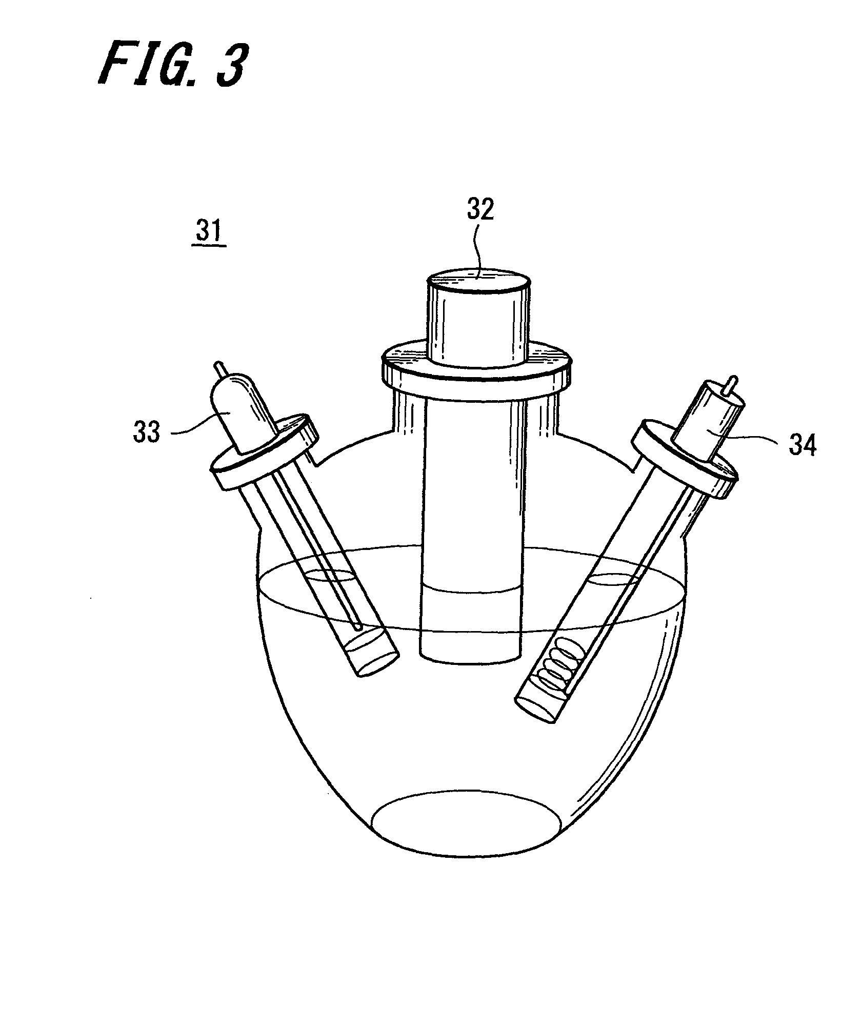
[0135]Acrylonitrile (manufactured by Wako Pure Chemical Industries, Ltd.) 30.93 g, methacrylic acid (manufactured by Wako Pure Chemical Industries, Ltd.) 4.07 g and pure water 300 ml were put into a four-necked flask, and bubbling was conducted for 15 minutes by using nitrogen gas. Next, the flask was immersed into an oil bath to adjust the temperature of the flask to 70° C. Further, a solution prepared by dissolving 100 mg of potassium peroxydisulfate (manufactured by Wako Pure Chemical Industries, Ltd.) in 50 ml of pure water was injected into the flask, which had been adjusted to 70° C., and stirred for four hours under a nitrogen gas atmosphere so as to be polymerized. Thereafter, the flask was cooled to obtain a milky-white solution.

[0136]Next, the milky-white solution was concentrated, and then the concentrated solution was vacuum-dried at a temperature of 60° C. to obtain about 20 g of polyacrylonitri...

example 2

[0147]Example 2 was identical to Example 1 except that the cobalt oxide in Example 1 was changed into the cobalt chloride (manufactured by Wako Pure Chemical Industries, Ltd.) and, in the preparation of the solution for spinning, the content of the cobalt chloride was 6% by mass based on the total solid content. The activity for oxygen reduction reaction of the carbon catalyst obtained in Example 2 was measured, and the value of the activity for oxygen reduction reaction is shown in Table 1.

example 3

Carbon Dioxide Activation

[0148]The nanofibers were carbonized using the same method as that of Example 1. After crushing treatment, the obtained carbon nanofibers were put into a quartz tube to be subjected to a carbon dioxide gas purge for 20 minutes in an ellipsoidal reflection type infrared gold image furnace, and then the temperature was raised from room temperature to 750° C. over 37 minutes. Thereafter, the temperature was held at 750° C. for one hour, and carbon dioxide activation was performed on the carbonized nanofibers. By using such a method, the carbon catalyst of Example 3 was obtained. The activity for oxygen reduction reaction of the carbon catalyst of Example 3 was measured, and the value of the activity for oxygen reduction reaction is shown in Table 1.


PUM

PropertyMeasurementUnit
diameteraaaaaaaaaa
thicknessaaaaaaaaaa
sizeaaaaaaaaaa

Abstract

The present invention is made to provide a carbon catalyst capable of preventing the coarsening of particles of nanoshell structure of carbon which causes reduction in activity for oxygen reduction reaction. The carbon catalyst is produced by the steps of: preparing a carbon precursor polymer; mixing a transition metal or a compound of the transition metal into the carbon precursor polymer; spinning the mixture of the carbon precursor polymer and the transition metal or the compound of the transition metal into fibers; and carbonizing the fibers.

Description

CROSS REFERENCES TO RELATED APPLICATIONS[0001]The present invention contains subject matter related to Japanese Patent Application JP 2008-27022 and Japanese Patent Application JP 2008-136828 respectively filed in the Japanese Patent Office on Feb. 6, 2008 and May 26, 2008, the entire contents of which being incorporated herein by reference.BACKGROUND OF THE INVENTION[0002]1. Field of the Invention[0003]The present invention relates to a carbon catalyst carrying no noble metal such as platinum, platinum alloy or the like, and also relates to a slurry containing the carbon catalyst, a method for producing the carbon catalyst, and a fuel cell, an electric storage device and an environmental catalyst each using the carbon catalyst.[0004]2. Description of the Related Art[0005]As one of the important solutions to global warming problem and environmental pollution problem, practical use of high-efficiency and pollution-free fuel cell has been attracting much attention.[0006]Particularly, ...

Claims


Application Information

Patent Timeline
Patent Type & Authority Applications(United States)
IPC IPC(8): B01J21/18C01B31/02C01B21/082C01B31/36C01B31/30H01M8/10B32B5/16B01J23/745B01J23/75B82Y30/00B82Y40/00B82Y99/00D01F9/22H01G11/22H01G11/40H01G11/44H01M4/88H01M4/90H01M4/96
CPCB01J21/18Y10T428/2982B01J27/24B01J35/06B01J37/08B82Y30/00C01B25/32C01B31/02H01G9/058H01G9/155H01G11/38H01G11/42H01M4/583H01M4/8605H01M4/96Y02E60/13Y02E60/50B01J21/185C01B32/05Y02E60/10H01G11/22
Inventor OZAKI, JUN-ICHISANDO, TERUKAZUHORIGUCHI, SHINICHIKISHIMOTO, TAKEAKISAITO, KAZUO
Owner GUNMA UNIVERSITY
Why Eureka
Try Eureka