Devices for cooling the nasal cavity

Active Publication Date: 2010-12-23
BRAINCOOL
View PDF75 Cites 62 Cited by
  • Summary
  • Abstract
  • Description
  • Claims
  • Application Information

AI Technical Summary

Benefits of technology

[0012]In use, the elongate member is inserted into a nasal cavity of a patient through one of the patient's nostrils and positioned in the nasal cavity. The elongate member may be positioned in the nasal cavity such that the balloon on the distal end of the elongate member will contact the walls of the posterior nasal cavity and form a seal between the nasal cavity and the patient's nasopharynx when inflated. Alternatively, the elongate tubular member may be positioned such that the balloon will contact the nasopharynx and form a seal between the nasal cavity and the patient's nasopharynx when inflated. The ports on the distal region of the elongate member will then be positioned to deliver a nebulized liquid spray over the surface of the nasal cavity, including the nasal plexus and the carotids. The proximal end of the elongate member is placed in fluid communication with a pressurized fluid source via a manifold. Pressure from the pressurized fluid source is used to push liquid and/or vapor from the pressurized fluid source into the elongate tubular member. The manifold controls delivery of the fluid to the elongate member such that liquid and/or vapor is first delivered through a lumen in fluid communication with the balloon mounted on the distal end of the elongate member to inflate the balloon. Once the balloon has been inflated, a check valve in the manifold opens and allows the fluid, including both liquid and vapor, to be delivered though a second lumen in fluid communication with the ports located on the distal region of the elongate member. A liquid spray

Problems solved by technology

Patients experiencing cerebral ischemia often suffer from disabilities ranging from transient neurological deficit to irreversible damage (stroke) or death.
The most common form of shock is cardiogenic shock, which results from severe depression of cardiac performance.
The most frequent cause of cardiogenic shock is myocardial infarction with loss of substantial muscle mass.
Pump failure can also result from acute myocarditis or from depression of myocardial contractility following cardiac arrest or prolonged cardiopulmonary bypass.
Mechanical abnormalities, such as severe valvular stenosis, massive aortic or mitral regurgitation, acutely acquired ventricular septal defects, can also cause cardiogenic shock by reducing cardiac o

Method used


Image

  • Devices for cooling the nasal cavity
  • Devices for cooling the nasal cavity
  • Devices for cooling the nasal cavity

Examples


Embodiment Construction

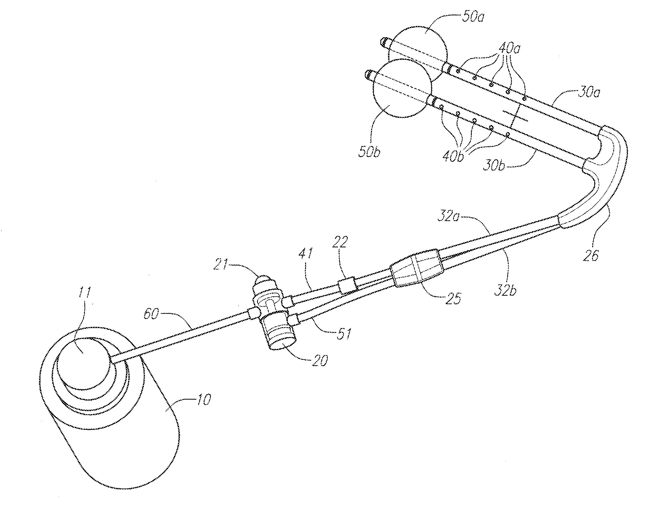
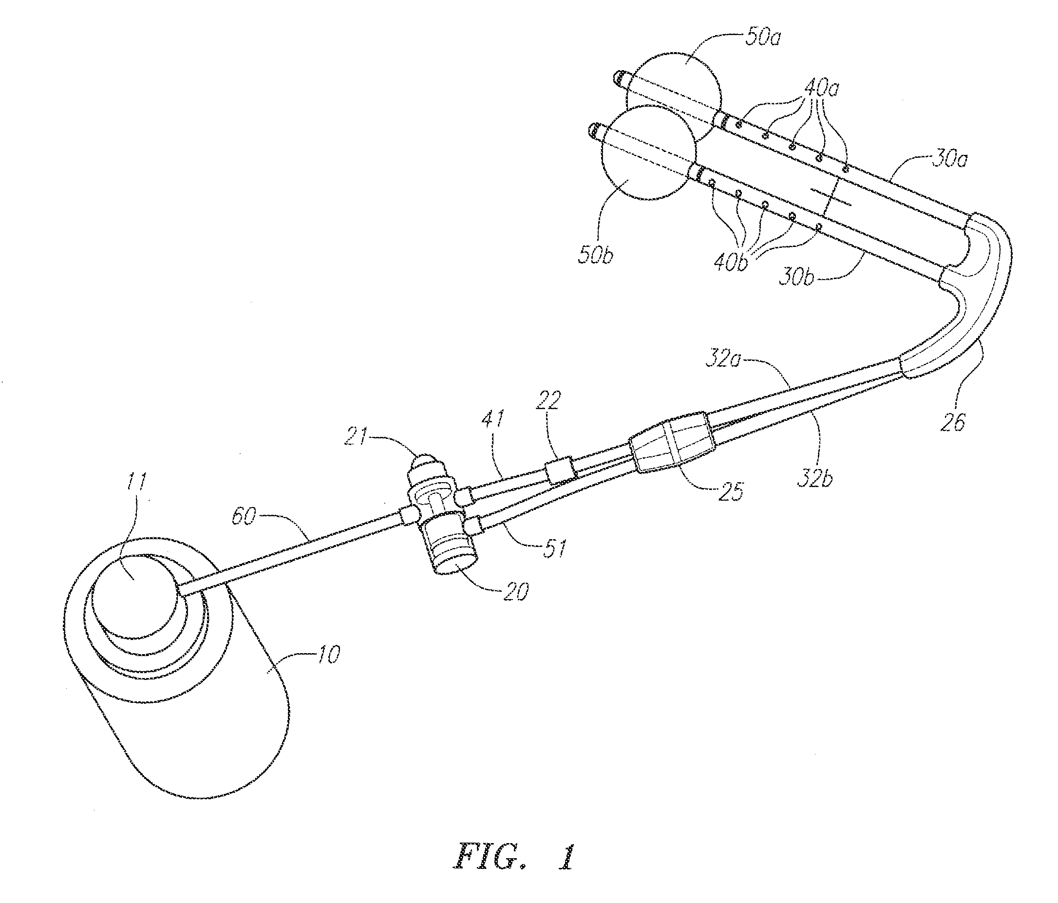
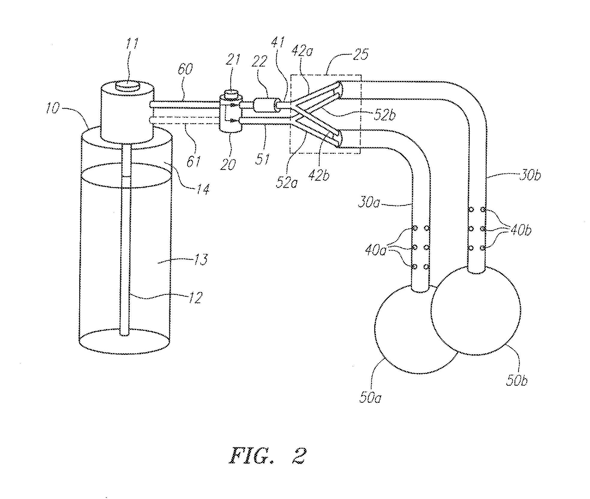
[0027]Described herein are devices and methods for delivering, from a pressurized source, a fluid that evaporates in the nasal cavity to provide cerebral and or systemic cooling. The approach is a self contained methodology which is designed for emergent care at the site of the injury. Essentially, this process provides a device and method for rapidly administering therapeutic hypothermia in an out-of-hospital setting, such as by emergency or ambulance personnel by developing an endothermic reaction within the nasal pharyngeal space, a mini-internal refrigeration unit. This approach eliminates the need for external refrigeration units, and large ventilation units which are not portable.

[0028]The device includes at least one nasal catheter in fluid communication with a pressurized fluid source for delivering a liquid spray of the fluid, which has a boiling point equal to or less than body temperature. In some embodiments, the device includes two nasal catheters such that one nasal ca...


PUM

PropertyMeasurementUnit
Boiling pointaaaaaaaaaa
Pressureaaaaaaaaaa

Abstract

A cerebral cooling device that uses a pressurized source to deliver a fluid that evaporates in the nasal cavity to provide cooling and has a balloon on the distal end that inflates from some of the pressure from the pressurized source. The device includes a nasal catheter having delivery ports located in the distal region and a balloon on the distal end. The proximal end of the catheter is in fluid communication with a pressurized source of a low boiling point fluid. A manifold located between the pressurized source and the catheter distributes the fluid and pressure from the pressurized source to a first lumen of the catheter to inflate the balloon and to a second lumen of the catheter through the delivery ports to cool the nasal cavity. A check valve in the manifold ensures that the fluid and pressure are first delivered to the balloon.

Description

[0001]This application claims the benefit of U.S. provisional patent application Ser. No. 61 / 218,774, entitled “Device for Cooling the Nasal cavity,” filed Jun. 19, 2009, which is expressly incorporated herein by reference in its entirety for all purposes.FIELD OF THE INVENTION[0002]The invention relates to cerebral and systemic cooling via the nasal cavity, oral cavity, and other parts of the body, and more particularly to methods and devices for cerebral and systemic cooling using liquids or liquid mists and for delivering liquid mists to the nasopharyngeal cavity.BACKGROUND OF THE INVENTION[0003]Patients experiencing cerebral ischemia often suffer from disabilities ranging from transient neurological deficit to irreversible damage (stroke) or death. Cerebral ischemia, i.e., reduction or cessation of blood flow to the central nervous system, can be characterized as either global or focal. Global cerebral ischemia refers to reduction of blood flow within the cerebral vasculature re...

Claims


Application Information

Patent Timeline
IPC IPC(8): A61F7/12A61M25/10A61M1/00A61F2/958
CPCA61F2007/0006A61M16/045A61F2007/0214A61F2007/0247A61M3/025A61M3/0295A61M13/003A61M16/208A61M25/10A61M2025/1052A61M2205/3606A61M2210/0618A61F7/12A61F7/123A61M16/0409A61F2007/0068A61M16/209A61M16/0461A61M16/0479A61M16/0486A61M3/022A61M3/0208A61M3/0245
Inventor ROZENBERG, ALLANHOFFMAN, JOHN K.SAVAGE, JAMES
Owner BRAINCOOL
Why Eureka
Try Eureka